Information injection-pump assembly
ZEXEL
101691-9661
1016919661
Rating:
Cross reference number
ZEXEL
101691-9661
1016919661
Zexel num
Bosch num
Firm num
Name
Calibration Data:
Adjustment conditions
Test oil
1404 Test oil ISO4113 or {SAEJ967d}
1404 Test oil ISO4113 or {SAEJ967d}
Test oil temperature
degC
40
40
45
Nozzle and nozzle holder
105780-8140
Bosch type code
EF8511/9A
Nozzle
105780-0000
Bosch type code
DN12SD12T
Nozzle holder
105780-2080
Bosch type code
EF8511/9
Opening pressure
MPa
17.2
Opening pressure
kgf/cm2
175
Injection pipe
Outer diameter - inner diameter - length (mm) mm 6-2-600
Outer diameter - inner diameter - length (mm) mm 6-2-600
Overflow valve opening pressure
kPa
157
123
191
Overflow valve opening pressure
kgf/cm2
1.6
1.25
1.95
Tester oil delivery pressure
kPa
157
157
157
Tester oil delivery pressure
kgf/cm2
1.6
1.6
1.6
Direction of rotation (viewed from drive side)
Right R
Right R
Injection timing adjustment
Direction of rotation (viewed from drive side)
Right R
Right R
Injection order
1-4-2-6-
3-5
Pre-stroke
mm
3.4
3.35
3.45
Beginning of injection position
Drive side NO.1
Drive side NO.1
Difference between angles 1
Cal 1-4 deg. 60 59.5 60.5
Cal 1-4 deg. 60 59.5 60.5
Difference between angles 2
Cyl.1-2 deg. 120 119.5 120.5
Cyl.1-2 deg. 120 119.5 120.5
Difference between angles 3
Cal 1-6 deg. 180 179.5 180.5
Cal 1-6 deg. 180 179.5 180.5
Difference between angles 4
Cal 1-3 deg. 240 239.5 240.5
Cal 1-3 deg. 240 239.5 240.5
Difference between angles 5
Cal 1-5 deg. 300 299.5 300.5
Cal 1-5 deg. 300 299.5 300.5
Injection quantity adjustment
Adjusting point
-
Rack position
12.2
Pump speed
r/min
1500
1500
1500
Average injection quantity
mm3/st.
73.5
71.9
75.1
Max. variation between cylinders
%
0
-3.5
3.5
Basic
*
Fixing the rack
*
Standard for adjustment of the maximum variation between cylinders
*
Injection quantity adjustment_02
Adjusting point
-
Rack position
9.7+-0.5
Pump speed
r/min
300
300
300
Average injection quantity
mm3/st.
9.5
7.7
11.3
Max. variation between cylinders
%
0
-10
10
Fixing the rack
*
Standard for adjustment of the maximum variation between cylinders
*
Remarks
Adjust only variation between cylinders; adjust governor according to governor specifications.
Adjust only variation between cylinders; adjust governor according to governor specifications.
Injection quantity adjustment_03
Adjusting point
A
Rack position
R1(12.2)
Pump speed
r/min
1500
1500
1500
Average injection quantity
mm3/st.
73.5
72.5
74.5
Basic
*
Fixing the lever
*
Injection quantity adjustment_04
Adjusting point
B
Rack position
R1-0.7
Pump speed
r/min
800
800
800
Average injection quantity
mm3/st.
54.7
52.7
56.7
Fixing the lever
*
Injection quantity adjustment_05
Adjusting point
I
Rack position
15.7+-0.
5
Pump speed
r/min
150
150
150
Average injection quantity
mm3/st.
77.5
77.5
97.5
Fixing the lever
*
Rack limit
*
Timer adjustment
Pump speed
r/min
1250--
Advance angle
deg.
0
0
0
Remarks
Start
Start
Timer adjustment_02
Pump speed
r/min
1200
Advance angle
deg.
0.5
Timer adjustment_03
Pump speed
r/min
1500
Advance angle
deg.
1
0.5
1.5
Remarks
Finish
Finish
Test data Ex:
Governor adjustment
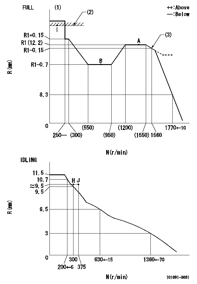
N:Pump speed
R:Rack position (mm)
(1)Torque cam stamping: T1
(2)RACK LIMIT
(3)Torque cam set point
----------
T1=C06
----------
----------
T1=C06
----------
Speed control lever angle

F:Full speed
I:Idle
(1)Stopper bolt set position 'H'
----------
----------
a=26.5deg+-5deg b=41deg+-3deg
----------
----------
a=26.5deg+-5deg b=41deg+-3deg
Stop lever angle

N:Pump normal
S:Stop the pump.
----------
----------
a=20deg+-5deg b=40deg+-5deg
----------
----------
a=20deg+-5deg b=40deg+-5deg
Timing setting

(1)Pump vertical direction
(2)Position of timer's threaded hole at No 1 cylinder's beginning of injection
(3)-
(4)-
----------
----------
a=(60deg)
----------
----------
a=(60deg)
Information:
Literature Information
This manual contains recommended safety procedures, fluid systems specifications, operation instructions, maintenance information and basic troubleshooting along with basic repair information and should be stored in the pilot house or engine area. Read, study and keep it in a literature holder or literature storage area with other literature and engine information.Some photographs or illustrations in this manual show details or attachments that may be different from your engine. Guards and covers may have been removed for illustrative purposes. Continuing improvement and advancement of product design may have caused changes to your engine which are not included in this manual. Whenever a question arises regarding your engine, or this manual, please consult your Caterpillar dealer for the latest available information.Safety
The safety section lists basic safety precautions. In addition, this section identifies hazardous, warning situations. Read and understand the basic precautions listed in the safety section before operating or performing lubrication, maintenance and repair on this product.Operation
Operating techniques outlined in this manual are basic to assist with developing the skills and techniques required to operate the engine more efficiently and economically. Skill and techniques develop as the pilot gains knowledge of the engine and its capabilities.The operation section is a reference for experienced pilots, and photographs and illustrations guide the new pilot through correct procedures of inspecting, starting, operating and stopping the engine. This section also includes a discussion of gauges, indicators, features and controls.Maintenance
The maintenance section is a guide to engine care. Items in the Maintenance Schedule are referenced to detailed instructions that follow. The instructions and procedures are grouped by fuel consumption, service hours and/or calendar time maintenance intervals.Use fuel consumption first to determine intervals. Calendar intervals shown (daily, annually, etc.) may be used instead of service meter intervals if they provide more convenient schedules and approximate the indicated service meter reading.Recommended service should always be performed at the fuel consumption interval first. The actual operating environment of the engine also governs the maintenance schedule. Therefore, under extremely severe or freezing cold operating conditions, more frequent lubrication and maintenance than is specified in the Maintenance Schedule may be necessary.Maintenance Intervals
Perform maintenance on items at multiples of the original requirement. Each level and/or individual items in each level should be shifted ahead or back depending upon your specific maintenance practices, operation and application. We recommend that the maintenance schedules be reproduced and displayed near the engine as a convenient reminder. We also recommend that a maintenance record be maintained as part of the engine's permanent record.See the Maintenance Records section in this manual for information regarding documents that are generally accepted as proof of maintenance or repair. Your authorized Caterpillar engine dealer can assist you in tailoring your Maintenance Schedule to meet the needs of your operating environment.Overhaul
Your Caterpillar dealer offers a variety of options regarding overhaul programs. If you experience a major engine failure which necessitates removal of the engine from the hull, there are also numerous after failure overhaul options available from your Caterpillar dealer. Contact