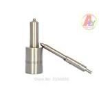
Information injection-pump assembly
ZEXEL
101691-9632
1016919632
Rating:
Service parts 101691-9632 INJECTION-PUMP ASSEMBLY:
1.
_
7.
COUPLING PLATE
8.
_
9.
_
11.
Nozzle and Holder
16600-95011
12.
Open Pre:MPa(Kqf/cm2)
19.6{200}
15.
NOZZLE SET
Include in #1:
101691-9632
as INJECTION-PUMP ASSEMBLY
Cross reference number
ZEXEL
101691-9632
1016919632
Zexel num
Bosch num
Firm num
Name
101691-9632
INJECTION-PUMP ASSEMBLY
Calibration Data:
Adjustment conditions
Test oil
1404 Test oil ISO4113 or {SAEJ967d}
1404 Test oil ISO4113 or {SAEJ967d}
Test oil temperature
degC
40
40
45
Nozzle and nozzle holder
105780-8140
Bosch type code
EF8511/9A
Nozzle
105780-0000
Bosch type code
DN12SD12T
Nozzle holder
105780-2080
Bosch type code
EF8511/9
Opening pressure
MPa
17.2
Opening pressure
kgf/cm2
175
Injection pipe
Outer diameter - inner diameter - length (mm) mm 6-2-600
Outer diameter - inner diameter - length (mm) mm 6-2-600
Overflow valve opening pressure
kPa
157
123
191
Overflow valve opening pressure
kgf/cm2
1.6
1.25
1.95
Tester oil delivery pressure
kPa
157
157
157
Tester oil delivery pressure
kgf/cm2
1.6
1.6
1.6
Direction of rotation (viewed from drive side)
Right R
Right R
Injection timing adjustment
Direction of rotation (viewed from drive side)
Right R
Right R
Injection order
1-4-2-6-
3-5
Pre-stroke
mm
3.7
3.65
3.75
Beginning of injection position
Drive side NO.1
Drive side NO.1
Difference between angles 1
Cal 1-4 deg. 60 59.5 60.5
Cal 1-4 deg. 60 59.5 60.5
Difference between angles 2
Cyl.1-2 deg. 120 119.5 120.5
Cyl.1-2 deg. 120 119.5 120.5
Difference between angles 3
Cal 1-6 deg. 180 179.5 180.5
Cal 1-6 deg. 180 179.5 180.5
Difference between angles 4
Cal 1-3 deg. 240 239.5 240.5
Cal 1-3 deg. 240 239.5 240.5
Difference between angles 5
Cal 1-5 deg. 300 299.5 300.5
Cal 1-5 deg. 300 299.5 300.5
Injection quantity adjustment
Adjusting point
-
Rack position
13.7
Pump speed
r/min
1400
1400
1400
Average injection quantity
mm3/st.
110.4
108.8
112
Max. variation between cylinders
%
0
-3.5
3.5
Basic
*
Fixing the rack
*
Standard for adjustment of the maximum variation between cylinders
*
Injection quantity adjustment_02
Adjusting point
-
Rack position
9.9+-0.5
Pump speed
r/min
275
275
275
Average injection quantity
mm3/st.
9
7.2
10.8
Max. variation between cylinders
%
0
-10
10
Fixing the rack
*
Standard for adjustment of the maximum variation between cylinders
*
Remarks
Adjust only variation between cylinders; adjust governor according to governor specifications.
Adjust only variation between cylinders; adjust governor according to governor specifications.
Injection quantity adjustment_03
Adjusting point
A
Rack position
R1(13.7)
Pump speed
r/min
1400
1400
1400
Average injection quantity
mm3/st.
110.4
109.4
111.4
Basic
*
Fixing the lever
*
Boost pressure
kPa
30.7
30.7
Boost pressure
mmHg
230
230
Injection quantity adjustment_04
Adjusting point
B
Rack position
R1+0.05
Pump speed
r/min
800
800
800
Average injection quantity
mm3/st.
103
101
105
Fixing the lever
*
Boost pressure
kPa
30.7
30.7
Boost pressure
mmHg
230
230
Injection quantity adjustment_05
Adjusting point
C
Rack position
R2(12.7)
Pump speed
r/min
400
400
400
Average injection quantity
mm3/st.
62.9
61.9
63.9
Fixing the lever
*
Boost pressure
kPa
0
0
0
Boost pressure
mmHg
0
0
0
Injection quantity adjustment_06
Adjusting point
I
Rack position
14.8+-0.
5
Pump speed
r/min
150
150
150
Average injection quantity
mm3/st.
80
80
100
Fixing the lever
*
Rack limit
*
Boost compensator adjustment
Pump speed
r/min
550
550
550
Rack position
(12)
Boost pressure
kPa
5.3
4
6.6
Boost pressure
mmHg
40
30
50
Boost compensator adjustment_02
Pump speed
r/min
550
550
550
Rack position
R1-1.4
Boost pressure
kPa
9.3
8
10.6
Boost pressure
mmHg
70
60
80
Boost compensator adjustment_03
Pump speed
r/min
550
550
550
Rack position
R1-0.65
Boost pressure
kPa
17.3
17.3
17.3
Boost pressure
mmHg
130
130
130
Timer adjustment
Pump speed
r/min
1200--
Advance angle
deg.
0
0
0
Remarks
Start
Start
Timer adjustment_02
Pump speed
r/min
1150
Advance angle
deg.
0.5
Timer adjustment_03
Pump speed
r/min
1400
Advance angle
deg.
2
1.5
2.5
Remarks
Finish
Finish
Test data Ex:
Governor adjustment
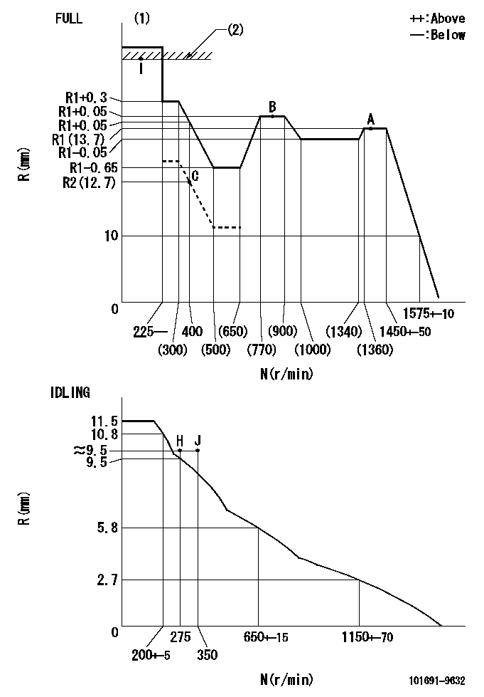
N:Pump speed
R:Rack position (mm)
(1)Torque cam stamping: T1
(2)RACK LIMIT
----------
T1=B84
----------
----------
T1=B84
----------
Speed control lever angle
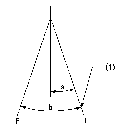
F:Full speed
I:Idle
(1)Stopper bolt set position 'H'
----------
----------
a=26.5deg+-5deg b=(43deg)+-3deg
----------
----------
a=26.5deg+-5deg b=(43deg)+-3deg
Stop lever angle
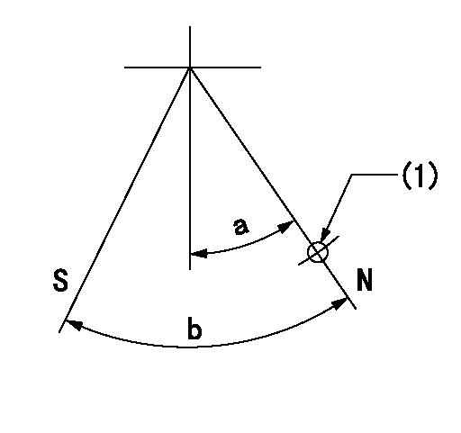
N:Pump normal
S:Stop the pump.
(1)Use the hole at R = aa
----------
aa=36mm
----------
a=20deg+-5deg b=40deg+-5deg
----------
aa=36mm
----------
a=20deg+-5deg b=40deg+-5deg
Timing setting

(1)Pump vertical direction
(2)Coupling's key groove position at No 1 cylinder's beginning of injection
(3)-
(4)-
----------
----------
a=(40deg)
----------
----------
a=(40deg)
Information:
Proper operation and maintenance are key factors in determining the useful life and economy of a truck engine. Follow the directions in this guide for trouble-free, economical truck engine operation. After the engine starts, reduce engine RPM to low idle with no load.(1674 and 1693: Before normal oil pressure is reached the governor control linkage travel is limited to below half engine speed by an oil pressure actuated stop inside the governor.) Do not attempt to force the governor control linkage past the stop. When normal oil pressure is reached, operate the engine at low load for 5 minutes before applying full load.Select the lowest gear for a smooth, easy start without slipping the clutch. Rapid engine acceleration causes heavy exhaust smoke and high fuel consumption with no increase in vehicle performance. For best performance, do not skip gears when loaded.Caterpillar engines have good lugging characteristics; however, avoid operating in a lug condition for extended periods of time as it causes exhaust temperatures to rise and results in high fuel consumption. A lug condition exists when an increase in engine speed cannot be achieved with an increase in accelerator pedal position, or when engine speed decreases with the accelerator pedal in its maximum position. A lug condition can exist at any engine speed below full load speed.Continue to upshift until cruising speed is reached. Cruising speed should be between three-fourths and full governed RPM. (The governor will maintain a constant speed without accelerator pedal correction.)On upgrade, begin downshifting if engine starts to labor. Downshift until a gear is reached in which the engine will pull the load without lugging. For best performance, downshift before engine RPM falls below peak torque RPM (see page 2).On downgrade, do not coast or put transmission in neutral. Select the correct gear to keep engine speed below idle and retard the vehicle. A simple rule to follow is to select the same gear that would be used to go up the grade. Do not allow engine speed to exceed high idle.Before stopping the engine, operate at low load for 5 minutes, then at low idle for 30 seconds. (This procedure allows hot areas in the engine to cool gradually, extending the engine life.) To stop the engine, use one of the methods listed. TO STOP THE ENGINE, DO ONE OF THE FOLLOWING, DEPENDING ON TRUCK ARRANGEMENT1. Turn the key to the spring-loaded position and hold until engine stops, then release key, or2. Pull out the manual shutoff control, or3. Push in and hold stop button until engine stops, then release button, or4. Pull up on the accelerator.
Have questions with 101691-9632?
Group cross 101691-9632 ZEXEL
Nissan-Diesel
Nissan-Diesel
Nissan-Diesel
Nissan-Diesel
101691-9632
INJECTION-PUMP ASSEMBLY
