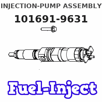
Information injection-pump assembly
ZEXEL
101691-9631
1016919631
NISSAN-DIESEL
1671395073
1671395073
Rating:
Cross reference number
ZEXEL
101691-9631
1016919631
NISSAN-DIESEL
1671395073
1671395073
Zexel num
Bosch num
Firm num
Name
Calibration Data:
Adjustment conditions
Test oil
1404 Test oil ISO4113 or {SAEJ967d}
1404 Test oil ISO4113 or {SAEJ967d}
Test oil temperature
degC
40
40
45
Nozzle and nozzle holder
105780-8140
Bosch type code
EF8511/9A
Nozzle
105780-0000
Bosch type code
DN12SD12T
Nozzle holder
105780-2080
Bosch type code
EF8511/9
Opening pressure
MPa
17.2
Opening pressure
kgf/cm2
175
Injection pipe
Outer diameter - inner diameter - length (mm) mm 6-2-600
Outer diameter - inner diameter - length (mm) mm 6-2-600
Overflow valve opening pressure
kPa
157
123
191
Overflow valve opening pressure
kgf/cm2
1.6
1.25
1.95
Tester oil delivery pressure
kPa
157
157
157
Tester oil delivery pressure
kgf/cm2
1.6
1.6
1.6
Direction of rotation (viewed from drive side)
Right R
Right R
Injection timing adjustment
Direction of rotation (viewed from drive side)
Right R
Right R
Injection order
1-4-2-6-
3-5
Pre-stroke
mm
3.7
3.65
3.75
Beginning of injection position
Drive side NO.1
Drive side NO.1
Difference between angles 1
Cal 1-4 deg. 60 59.5 60.5
Cal 1-4 deg. 60 59.5 60.5
Difference between angles 2
Cyl.1-2 deg. 120 119.5 120.5
Cyl.1-2 deg. 120 119.5 120.5
Difference between angles 3
Cal 1-6 deg. 180 179.5 180.5
Cal 1-6 deg. 180 179.5 180.5
Difference between angles 4
Cal 1-3 deg. 240 239.5 240.5
Cal 1-3 deg. 240 239.5 240.5
Difference between angles 5
Cal 1-5 deg. 300 299.5 300.5
Cal 1-5 deg. 300 299.5 300.5
Injection quantity adjustment
Adjusting point
-
Rack position
13.7
Pump speed
r/min
1400
1400
1400
Average injection quantity
mm3/st.
110.4
108.8
112
Max. variation between cylinders
%
0
-3.5
3.5
Basic
*
Fixing the rack
*
Standard for adjustment of the maximum variation between cylinders
*
Injection quantity adjustment_02
Adjusting point
-
Rack position
9.9+-0.5
Pump speed
r/min
275
275
275
Average injection quantity
mm3/st.
9
7.2
10.8
Max. variation between cylinders
%
0
-10
10
Fixing the rack
*
Standard for adjustment of the maximum variation between cylinders
*
Remarks
Adjust only variation between cylinders; adjust governor according to governor specifications.
Adjust only variation between cylinders; adjust governor according to governor specifications.
Injection quantity adjustment_03
Adjusting point
A
Rack position
R1(13.7)
Pump speed
r/min
1400
1400
1400
Average injection quantity
mm3/st.
110.4
109.4
111.4
Basic
*
Fixing the lever
*
Boost pressure
kPa
30.7
30.7
Boost pressure
mmHg
230
230
Injection quantity adjustment_04
Adjusting point
B
Rack position
R1+0.05
Pump speed
r/min
800
800
800
Average injection quantity
mm3/st.
103
101
105
Fixing the lever
*
Boost pressure
kPa
30.7
30.7
Boost pressure
mmHg
230
230
Injection quantity adjustment_05
Adjusting point
C
Rack position
R2(12.7)
Pump speed
r/min
400
400
400
Average injection quantity
mm3/st.
62.9
61.9
63.9
Fixing the lever
*
Boost pressure
kPa
0
0
0
Boost pressure
mmHg
0
0
0
Injection quantity adjustment_06
Adjusting point
I
Rack position
14.8+-0.
5
Pump speed
r/min
150
150
150
Average injection quantity
mm3/st.
80
80
100
Fixing the lever
*
Rack limit
*
Boost compensator adjustment
Pump speed
r/min
550
550
550
Rack position
(12)
Boost pressure
kPa
5.3
4
6.6
Boost pressure
mmHg
40
30
50
Boost compensator adjustment_02
Pump speed
r/min
550
550
550
Rack position
R1-1.4
Boost pressure
kPa
9.3
8
10.6
Boost pressure
mmHg
70
60
80
Boost compensator adjustment_03
Pump speed
r/min
550
550
550
Rack position
R1-0.65
Boost pressure
kPa
17.3
17.3
17.3
Boost pressure
mmHg
130
130
130
Timer adjustment
Pump speed
r/min
1200--
Advance angle
deg.
0
0
0
Remarks
Start
Start
Timer adjustment_02
Pump speed
r/min
1150
Advance angle
deg.
0.5
Timer adjustment_03
Pump speed
r/min
1400
Advance angle
deg.
2
1.5
2.5
Remarks
Finish
Finish
Test data Ex:
Governor adjustment
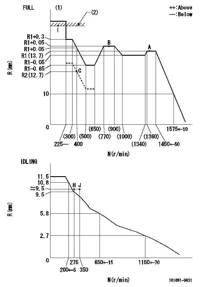
N:Pump speed
R:Rack position (mm)
(1)Torque cam stamping: T1
(2)RACK LIMIT
----------
T1=B84
----------
----------
T1=B84
----------
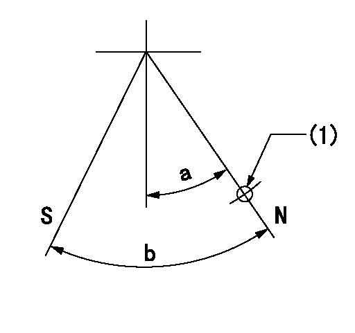
Speed control lever angle

F:Full speed
I:Idle
(1)Stopper bolt set position 'H'
----------
----------
a=26.5deg+-5deg b=(43deg)+-3deg
----------
----------
a=26.5deg+-5deg b=(43deg)+-3deg
Stop lever angle
N:Pump normal
S:Stop the pump.
(1)Use the hole at R = aa
----------
aa=36mm
----------
a=20deg+-5deg b=40deg+-5deg
----------
aa=36mm
----------
a=20deg+-5deg b=40deg+-5deg
Timing setting

(1)Pump vertical direction
(2)Coupling's key groove position at No 1 cylinder's beginning of injection
(3)-
(4)-
----------
----------
a=(40deg)
----------
----------
a=(40deg)
Information:
1. Engine Fails to Start2. Misfiring3. Stalls at Low Speed4. Erratic Engine Speed5. Low Power6. Excessive Vibration7. Heavy Combustion Knock8. Valve Train Clicking Knock9. Oil in Coolant10. Mechanical Knock11. Excessive Fuel Consumption12. Loud Valve Train Noise13. Excessive Valve Lash14. Valve Spring Retainer Free15. Slobber16. Valve Lash Close-up17. Premature Engine Wear18. Coolant in Engine Lubricating Oil19. Excessive Black or Grey Smoke20. Excessive White or Blue Smoke21. Low Engine Oil Pressure22. High Lubricating Oil Consumption23. Abnormal Engine Coolant Temperature24. Starting Motor Fails to Crank25. Alternator Fails to Charge26. Alternator Charging Rate Low or Unsteady27. Alternator Charging Rate High28. Alternator Noisy 1. ENGINE FAILS TO START 2. MISFIRING 3. STALLS AT LOW SPEED 4. ERRATIC ENGINE SPEED 5. LOW POWER 6. EXCESSIVE VIBRATION 7. HEAVY COMBUSTION KNOCK 8. VALVE TRAIN CLICKING NOISE 9. OIL IN COOLANT 10. MECHANICAL KNOCK 11. EXCESSIVE FUEL CONSUMPTION 12. LOUD VALVE TRAIN NOISE 13. EXCESSIVE VALVE LASH 14. VALVE SPRING RETAINER FREE 15. SLOBBER 16. VALVE LASH CLOSE-UP 17. PREMATURE ENGINE WEAR 18. COOLANT IN ENGINE LUBRICATING OIL 19. Excessive Black Or Gray Smoke 20. Excessive White Or Blue Smoke 21. Low Engine Oil Pressure 22. High Lubricating Oil Consumption 23. Abnormal Engine Coolant Temperature 24. Starting Motor Fails To Crank 25. Alternator Fails To Charge 26. Alternator Charging Rate Low Or Unsteady 27. Alternator Charging Rate High 28. Alternator Noisy *Authorized dealers are equipped with the necessary tools and personnel familiar with disassembly and assembly procedures to perform these serviced.