Information injection-pump assembly
ZEXEL
101691-9621
1016919621
NISSAN-DIESEL
1671395072
1671395072
Rating:
Cross reference number
ZEXEL
101691-9621
1016919621
NISSAN-DIESEL
1671395072
1671395072
Zexel num
Bosch num
Firm num
Name
Calibration Data:
Adjustment conditions
Test oil
1404 Test oil ISO4113 or {SAEJ967d}
1404 Test oil ISO4113 or {SAEJ967d}
Test oil temperature
degC
40
40
45
Nozzle and nozzle holder
105780-8140
Bosch type code
EF8511/9A
Nozzle
105780-0000
Bosch type code
DN12SD12T
Nozzle holder
105780-2080
Bosch type code
EF8511/9
Opening pressure
MPa
17.2
Opening pressure
kgf/cm2
175
Injection pipe
Outer diameter - inner diameter - length (mm) mm 6-2-600
Outer diameter - inner diameter - length (mm) mm 6-2-600
Overflow valve opening pressure
kPa
157
123
191
Overflow valve opening pressure
kgf/cm2
1.6
1.25
1.95
Tester oil delivery pressure
kPa
157
157
157
Tester oil delivery pressure
kgf/cm2
1.6
1.6
1.6
Direction of rotation (viewed from drive side)
Right R
Right R
Injection timing adjustment
Direction of rotation (viewed from drive side)
Right R
Right R
Injection order
1-4-2-6-
3-5
Pre-stroke
mm
3.7
3.65
3.75
Beginning of injection position
Drive side NO.1
Drive side NO.1
Difference between angles 1
Cal 1-4 deg. 60 59.5 60.5
Cal 1-4 deg. 60 59.5 60.5
Difference between angles 2
Cyl.1-2 deg. 120 119.5 120.5
Cyl.1-2 deg. 120 119.5 120.5
Difference between angles 3
Cal 1-6 deg. 180 179.5 180.5
Cal 1-6 deg. 180 179.5 180.5
Difference between angles 4
Cal 1-3 deg. 240 239.5 240.5
Cal 1-3 deg. 240 239.5 240.5
Difference between angles 5
Cal 1-5 deg. 300 299.5 300.5
Cal 1-5 deg. 300 299.5 300.5
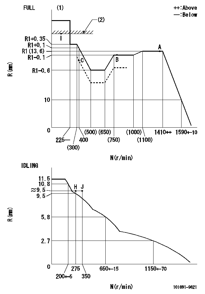
Injection quantity adjustment
Adjusting point
-
Rack position
13.6
Pump speed
r/min
1400
1400
1400
Average injection quantity
mm3/st.
106.4
104.8
108
Max. variation between cylinders
%
0
-3.5
3.5
Basic
*
Fixing the rack
*
Standard for adjustment of the maximum variation between cylinders
*
Injection quantity adjustment_02
Adjusting point
-
Rack position
9.9+-0.5
Pump speed
r/min
275
275
275
Average injection quantity
mm3/st.
9
7.2
10.8
Max. variation between cylinders
%
0
-10
10
Fixing the rack
*
Standard for adjustment of the maximum variation between cylinders
*
Remarks
Adjust only variation between cylinders; adjust governor according to governor specifications.
Adjust only variation between cylinders; adjust governor according to governor specifications.
Injection quantity adjustment_03
Adjusting point
A
Rack position
R1(13.6)
Pump speed
r/min
1400
1400
1400
Average injection quantity
mm3/st.
106.4
105.4
107.4
Basic
*
Fixing the lever
*
Boost pressure
kPa
29.3
29.3
Boost pressure
mmHg
220
220
Injection quantity adjustment_04
Adjusting point
B
Rack position
R1-0.1
Pump speed
r/min
800
800
800
Average injection quantity
mm3/st.
96.7
93.5
99.9
Fixing the lever
*
Boost pressure
kPa
29.3
29.3
Boost pressure
mmHg
220
220
Injection quantity adjustment_05
Adjusting point
C
Rack position
R2(12.7)
Pump speed
r/min
400
400
400
Average injection quantity
mm3/st.
62.9
61.9
63.9
Fixing the lever
*
Boost pressure
kPa
0
0
0
Boost pressure
mmHg
0
0
0
Injection quantity adjustment_06
Adjusting point
I
Rack position
14.8+-0.
5
Pump speed
r/min
150
150
150
Average injection quantity
mm3/st.
80
80
100
Fixing the lever
*
Rack limit
*
Boost compensator adjustment
Pump speed
r/min
400
400
400
Rack position
R2(12.7)
Boost pressure
kPa
4
2.7
5.3
Boost pressure
mmHg
30
20
40
Boost compensator adjustment_02
Pump speed
r/min
400
400
400
Rack position
R1-0.5
Boost pressure
kPa
9.3
8
10.6
Boost pressure
mmHg
70
60
80
Boost compensator adjustment_03
Pump speed
r/min
400
400
400
Rack position
R1+0.1
Boost pressure
kPa
16
16
16
Boost pressure
mmHg
120
120
120
Timer adjustment
Pump speed
r/min
920--
Advance angle
deg.
0
0
0
Remarks
Start
Start
Timer adjustment_02
Pump speed
r/min
870
Advance angle
deg.
0.5
Timer adjustment_03
Pump speed
r/min
1400
Advance angle
deg.
2
1.5
2.5
Remarks
Finish
Finish
Test data Ex:
Governor adjustment
N:Pump speed
R:Rack position (mm)
(1)Torque cam stamping: T1
(2)RACK LIMIT
----------
T1=B36
----------
----------
T1=B36
----------
Speed control lever angle

F:Full speed
I:Idle
(1)Stopper bolt setting
----------
----------
a=26.5deg+-5deg b=43deg+-3deg
----------
----------
a=26.5deg+-5deg b=43deg+-3deg
Stop lever angle
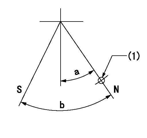
N:Pump normal
S:Stop the pump.
(1)Use the hole at R = aa
----------
aa=36mm
----------
a=20deg+-5deg b=40deg+-5deg
----------
aa=36mm
----------
a=20deg+-5deg b=40deg+-5deg
Timing setting

(1)Pump vertical direction
(2)Coupling's key groove position at No 1 cylinder's beginning of injection
(3)-
(4)-
----------
----------
a=(40deg)
----------
----------
a=(40deg)
Information:
Flywheel And/Or Front Power Take-Off Clutches
Checking Clutch Adjustment
While engaging the clutch to pick up the load, check the clutch adjustment. The clutch should engage with a hard push and distinct snap. If engagement is "soft", adjust the clutch.Adjusting Clutch Engagement
1. Stop the engine and remove the clutch inspection cover. 2. Turn the clutch until the lock pin, engaged in the locking ring, is visible.3. Pull the lock pin out and rotate the locking ring clockwise until the lock pin pops into the next notch. 4. Test the clutch adjustment. If still too "soft", rotate the ring to the next notch. If the adjustment is too tight-turn the ring back one notch.5. Install the cover.Generator Set
Your electric set engine may be equipped with a Caterpillar SR4 Generator. The SR4 Generator is a brushless design, and therefore requires no periodic maintenance other than lubrication of the rear bearing. See Lubrication Instructions.The generator serial number is stamped on the generator housing. The first group of numbers, reading from the left, indicates the frame size. Following this number are the letters BS, BH or BG. The letter B indicates the generator is of the SR4 design. The letter S, H or G indicates the voltage rating of the generator. The following numerical digits are the serial number of the generator in that particular frame size and voltage rating. A complete explanation of the numbers and letters in the serial number are found in the GENERATOR SET SYSTEMS OPERATION SECTION. Always use the complete serial number in your communications with your Caterpillar dealer.If you have a generator of other than Caterpillar design, see the Manufacturer's Instructions.
GENERATOR SERIAL NUMBER LOCATION