Information injection-pump assembly
ZEXEL
101691-9603
1016919603
Rating:
Service parts 101691-9603 INJECTION-PUMP ASSEMBLY:
1.
_
7.
COUPLING PLATE
8.
_
9.
_
11.
Nozzle and Holder
16600-95011
12.
Open Pre:MPa(Kqf/cm2)
19.6{200}

15.
NOZZLE SET
Include in #1:
101691-9603
as INJECTION-PUMP ASSEMBLY
Cross reference number
ZEXEL
101691-9603
1016919603
Zexel num
Bosch num
Firm num
Name
101691-9603
INJECTION-PUMP ASSEMBLY
Calibration Data:
Adjustment conditions
Test oil
1404 Test oil ISO4113 or {SAEJ967d}
1404 Test oil ISO4113 or {SAEJ967d}
Test oil temperature
degC
40
40
45
Nozzle and nozzle holder
105780-8140
Bosch type code
EF8511/9A
Nozzle
105780-0000
Bosch type code
DN12SD12T
Nozzle holder
105780-2080
Bosch type code
EF8511/9
Opening pressure
MPa
17.2
Opening pressure
kgf/cm2
175
Injection pipe
Outer diameter - inner diameter - length (mm) mm 6-2-600
Outer diameter - inner diameter - length (mm) mm 6-2-600
Overflow valve opening pressure
kPa
157
123
191
Overflow valve opening pressure
kgf/cm2
1.6
1.25
1.95
Tester oil delivery pressure
kPa
157
157
157
Tester oil delivery pressure
kgf/cm2
1.6
1.6
1.6
Direction of rotation (viewed from drive side)
Right R
Right R
Injection timing adjustment
Direction of rotation (viewed from drive side)
Right R
Right R
Injection order
1-4-2-6-
3-5
Pre-stroke
mm
3.7
3.65
3.75
Beginning of injection position
Drive side NO.1
Drive side NO.1
Difference between angles 1
Cal 1-4 deg. 60 59.5 60.5
Cal 1-4 deg. 60 59.5 60.5
Difference between angles 2
Cyl.1-2 deg. 120 119.5 120.5
Cyl.1-2 deg. 120 119.5 120.5
Difference between angles 3
Cal 1-6 deg. 180 179.5 180.5
Cal 1-6 deg. 180 179.5 180.5
Difference between angles 4
Cal 1-3 deg. 240 239.5 240.5
Cal 1-3 deg. 240 239.5 240.5
Difference between angles 5
Cal 1-5 deg. 300 299.5 300.5
Cal 1-5 deg. 300 299.5 300.5
Injection quantity adjustment
Adjusting point
-
Rack position
13.6
Pump speed
r/min
1400
1400
1400
Average injection quantity
mm3/st.
106.4
104.8
108
Max. variation between cylinders
%
0
-3.5
3.5
Basic
*
Fixing the rack
*
Standard for adjustment of the maximum variation between cylinders
*
Injection quantity adjustment_02
Adjusting point
-
Rack position
9.9+-0.5
Pump speed
r/min
275
275
275
Average injection quantity
mm3/st.
9
7.2
10.8
Max. variation between cylinders
%
0
-10
10
Fixing the rack
*
Standard for adjustment of the maximum variation between cylinders
*
Remarks
Adjust only variation between cylinders; adjust governor according to governor specifications.
Adjust only variation between cylinders; adjust governor according to governor specifications.
Injection quantity adjustment_03
Adjusting point
A
Rack position
R1(13.6)
Pump speed
r/min
1400
1400
1400
Average injection quantity
mm3/st.
106.4
105.4
107.4
Basic
*
Fixing the lever
*
Boost pressure
kPa
29.3
29.3
Boost pressure
mmHg
220
220
Injection quantity adjustment_04
Adjusting point
B
Rack position
R1-0.1
Pump speed
r/min
800
800
800
Average injection quantity
mm3/st.
96.7
93.5
99.9
Fixing the lever
*
Boost pressure
kPa
29.3
29.3
Boost pressure
mmHg
220
220
Injection quantity adjustment_05
Adjusting point
C
Rack position
R2(12.7)
Pump speed
r/min
400
400
400
Average injection quantity
mm3/st.
62.9
61.9
63.9
Fixing the lever
*
Boost pressure
kPa
0
0
0
Boost pressure
mmHg
0
0
0
Injection quantity adjustment_06
Adjusting point
I
Rack position
14.8+-0.
5
Pump speed
r/min
150
150
150
Average injection quantity
mm3/st.
80
80
100
Fixing the lever
*
Rack limit
*
Boost compensator adjustment
Pump speed
r/min
400
400
400
Rack position
R2(12.7)
Boost pressure
kPa
4
2.7
5.3
Boost pressure
mmHg
30
20
40
Boost compensator adjustment_02
Pump speed
r/min
400
400
400
Rack position
R1-0.5
Boost pressure
kPa
9.3
8
10.6
Boost pressure
mmHg
70
60
80
Boost compensator adjustment_03
Pump speed
r/min
400
400
400
Rack position
R1+0.1
Boost pressure
kPa
16
16
16
Boost pressure
mmHg
120
120
120
Timer adjustment
Pump speed
r/min
920--
Advance angle
deg.
0
0
0
Remarks
Start
Start
Timer adjustment_02
Pump speed
r/min
870
Advance angle
deg.
0.5
Timer adjustment_03
Pump speed
r/min
1400
Advance angle
deg.
2
1.5
2.5
Remarks
Finish
Finish
Test data Ex:
Governor adjustment
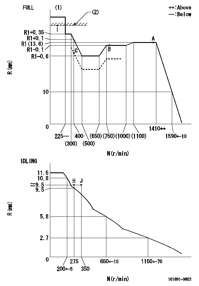
N:Pump speed
R:Rack position (mm)
(1)Torque cam stamping: T1
(2)RACK LIMIT
----------
T1=B36
----------
----------
T1=B36
----------
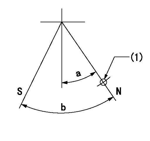
Speed control lever angle

F:Full speed
I:Idle
(1)Stopper bolt set position 'H'
----------
----------
a=26.5deg+-5deg b=43deg+-3deg
----------
----------
a=26.5deg+-5deg b=43deg+-3deg
Stop lever angle
N:Pump normal
S:Stop the pump.
(1)Use the hole at R = aa
----------
aa=36mm
----------
a=20deg+-5deg b=40deg+-5deg
----------
aa=36mm
----------
a=20deg+-5deg b=40deg+-5deg
Timing setting

(1)Pump vertical direction
(2)Coupling's key groove position at No 1 cylinder's beginning of injection
(3)-
(4)-
----------
----------
a=(40deg)
----------
----------
a=(40deg)
Information:
Be sure to read the correct side of the dipstick. The ADD and FULL levels are not the same when checking the oil while stopped or while idling.
Checking Oil Pressure
Immediately after starting, and frequently during operation, observe the oil pressure gauge reading. The indicator should register in the NORMAL range. If the indicator fluctuates or registers below NORMAL range:1. Move the governor control to low idle position.2. Check the oil level. Be sure to read the ENGINE IDLING side of the dipstick.3. Add oil until the oil level is at the FULL mark on the ENGINE IDLING side of the dipstick. Do not overfill.4. Check for oil leaks.5. If necessary, stop the engine and have repairs made.Draining Engine Oil
With engine stopped and oil warm:1. Remove the crankcase oil drain plug.2. Allow the oil to drain. 3. Clean and install the drain plug.OR, if a sump pump is used:1. Connect a suitable drain line and container to the pump outlet.2. With engine stopped and oil warm, open the sump pump valve to the engine crankcase drain line: The two marks on the valve must be turned so that one mark points to the pump, and the second mark points to the engine drain line.3. Operate the sump pump handle until the crankcase is empty.4. Close the valve to the engine crankcase drain line.Cleaning the Breather
1. Release the hose clamp and disconnect the fumes disposal tube.2. Remove the breather assembly. 3. Wash the breather in solvent.4. Allow to drain dry and then wipe.5. Inspect the gasket. Install a new gasket if necessary.6. Install the breather.7. Connect the fumes disposal tube. Changing Oil Filter
1. Unscrew and remove the filter. 2. Be sure the old filter gasket did not remain attached inside the filter base: Leaking will occur between the new filter gasket and this old gasket.3. Wipe the filter base. 4. Apply a thin coat of clean oil to the gasket of the new filter. 5. Install the new filter: Hand tighten the filter 3/4turn after the filter gasket contacts the base. Use rotation index numbers, which are painted on the filter can, as a guide for proper tightening. Filling the Crankcase
1. Fill the crankcase to the safe starting range on the ENGINE STOPPED side of the dipstick. See the Lubrication Specifications for refill capacity and proper oil viscosity. 2. Start the engine and check for oil leaks.3. After the engine is warm, check the oil level with the engine idling.4. Add oil if necessary to maintain the oil level at the FULL mark on the ENGINE IDLING side of the dipstick.Fan Drive Bearings
Lubricate the fan drive bearings with lubricating grease through one fitting, 1 or 2 strokes.
LOCATION OF 4B4550 PRESSURE RELIEF FITTING AND 2D4867 FITTING SHOWN IN THE STANDARD LOCATION.If the grease fitting is not readily accessible, it may be necessary to1. Remove the 4B4550 Fitting (relief) from the fan mounting bracket assembly and install the 2D4867 Fitting in its place.2. Install the 4B4550 Fitting (relief) in place of the
Have questions with 101691-9603?
Group cross 101691-9603 ZEXEL
Nissan-Diesel
101691-9603
INJECTION-PUMP ASSEMBLY