Information injection-pump assembly
ZEXEL
101691-9602
1016919602
NISSAN-DIESEL
1671395069
1671395069
Rating:
Cross reference number
ZEXEL
101691-9602
1016919602
NISSAN-DIESEL
1671395069
1671395069
Zexel num
Bosch num
Firm num
Name
Calibration Data:
Adjustment conditions
Test oil
1404 Test oil ISO4113 or {SAEJ967d}
1404 Test oil ISO4113 or {SAEJ967d}
Test oil temperature
degC
40
40
45
Nozzle and nozzle holder
105780-8140
Bosch type code
EF8511/9A
Nozzle
105780-0000
Bosch type code
DN12SD12T
Nozzle holder
105780-2080
Bosch type code
EF8511/9
Opening pressure
MPa
17.2
Opening pressure
kgf/cm2
175
Injection pipe
Outer diameter - inner diameter - length (mm) mm 6-2-600
Outer diameter - inner diameter - length (mm) mm 6-2-600
Overflow valve opening pressure
kPa
157
123
191
Overflow valve opening pressure
kgf/cm2
1.6
1.25
1.95
Tester oil delivery pressure
kPa
157
157
157
Tester oil delivery pressure
kgf/cm2
1.6
1.6
1.6
Direction of rotation (viewed from drive side)
Right R
Right R
Injection timing adjustment
Direction of rotation (viewed from drive side)
Right R
Right R
Injection order
1-4-2-6-
3-5
Pre-stroke
mm
3.7
3.65
3.75
Beginning of injection position
Drive side NO.1
Drive side NO.1
Difference between angles 1
Cal 1-4 deg. 60 59.5 60.5
Cal 1-4 deg. 60 59.5 60.5
Difference between angles 2
Cyl.1-2 deg. 120 119.5 120.5
Cyl.1-2 deg. 120 119.5 120.5
Difference between angles 3
Cal 1-6 deg. 180 179.5 180.5
Cal 1-6 deg. 180 179.5 180.5
Difference between angles 4
Cal 1-3 deg. 240 239.5 240.5
Cal 1-3 deg. 240 239.5 240.5
Difference between angles 5
Cal 1-5 deg. 300 299.5 300.5
Cal 1-5 deg. 300 299.5 300.5
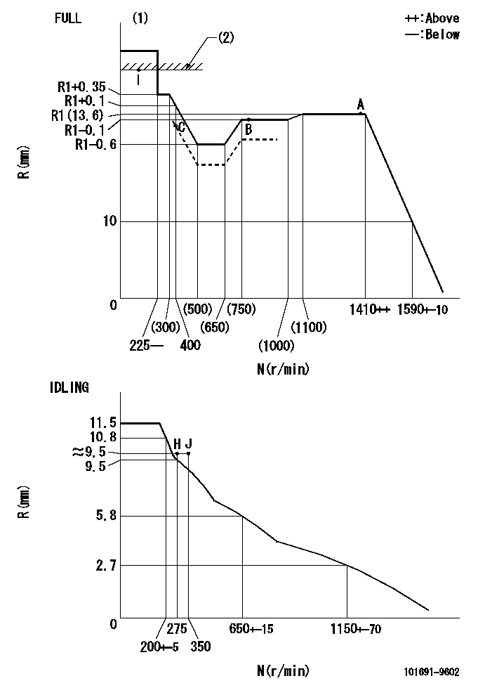
Injection quantity adjustment
Adjusting point
-
Rack position
13.6
Pump speed
r/min
1400
1400
1400
Average injection quantity
mm3/st.
106.4
104.8
108
Max. variation between cylinders
%
0
-3.5
3.5
Basic
*
Fixing the rack
*
Standard for adjustment of the maximum variation between cylinders
*
Injection quantity adjustment_02
Adjusting point
-
Rack position
9.9+-0.5
Pump speed
r/min
275
275
275
Average injection quantity
mm3/st.
9
7.2
10.8
Max. variation between cylinders
%
0
-10
10
Fixing the rack
*
Standard for adjustment of the maximum variation between cylinders
*
Remarks
Adjust only variation between cylinders; adjust governor according to governor specifications.
Adjust only variation between cylinders; adjust governor according to governor specifications.
Injection quantity adjustment_03
Adjusting point
A
Rack position
R1(13.6)
Pump speed
r/min
1400
1400
1400
Average injection quantity
mm3/st.
106.4
105.4
107.4
Basic
*
Fixing the lever
*
Boost pressure
kPa
29.3
29.3
Boost pressure
mmHg
220
220
Injection quantity adjustment_04
Adjusting point
B
Rack position
R1-0.1
Pump speed
r/min
800
800
800
Average injection quantity
mm3/st.
96.7
93.5
99.9
Fixing the lever
*
Boost pressure
kPa
29.3
29.3
Boost pressure
mmHg
220
220
Injection quantity adjustment_05
Adjusting point
C
Rack position
R2(12.7)
Pump speed
r/min
400
400
400
Average injection quantity
mm3/st.
62.9
61.9
63.9
Fixing the lever
*
Boost pressure
kPa
0
0
0
Boost pressure
mmHg
0
0
0
Injection quantity adjustment_06
Adjusting point
I
Rack position
14.8+-0.
5
Pump speed
r/min
150
150
150
Average injection quantity
mm3/st.
80
80
100
Fixing the lever
*
Rack limit
*
Boost compensator adjustment
Pump speed
r/min
400
400
400
Rack position
R2(12.7)
Boost pressure
kPa
4
2.7
5.3
Boost pressure
mmHg
30
20
40
Boost compensator adjustment_02
Pump speed
r/min
400
400
400
Rack position
R1-0.5
Boost pressure
kPa
9.3
8
10.6
Boost pressure
mmHg
70
60
80
Boost compensator adjustment_03
Pump speed
r/min
400
400
400
Rack position
R1+0.1
Boost pressure
kPa
16
16
16
Boost pressure
mmHg
120
120
120
Timer adjustment
Pump speed
r/min
920--
Advance angle
deg.
0
0
0
Remarks
Start
Start
Timer adjustment_02
Pump speed
r/min
870
Advance angle
deg.
0.5
Timer adjustment_03
Pump speed
r/min
1400
Advance angle
deg.
2
1.5
2.5
Remarks
Finish
Finish
Test data Ex:
Governor adjustment
N:Pump speed
R:Rack position (mm)
(1)Torque cam stamping: T1
(2)RACK LIMIT
----------
T1=B36
----------
----------
T1=B36
----------
Speed control lever angle

F:Full speed
I:Idle
(1)Stopper bolt set position 'H'
----------
----------
a=26.5deg+-5deg b=43deg+-3deg
----------
----------
a=26.5deg+-5deg b=43deg+-3deg
Stop lever angle
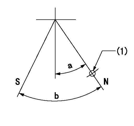
N:Pump normal
S:Stop the pump.
(1)Use the hole at R = aa
----------
aa=36mm
----------
a=20deg+-5deg b=40deg+-5deg
----------
aa=36mm
----------
a=20deg+-5deg b=40deg+-5deg
Timing setting

(1)Pump vertical direction
(2)Coupling's key groove position at No 1 cylinder's beginning of injection
(3)-
(4)-
----------
----------
a=(40deg)
----------
----------
a=(40deg)
Information:
Regular service intervals, along with close daily visual inspection and the adherence to the instructions and schedules, will assure many hours of trouble-free service. If correction steps are taken immediately on discovery of any abnormal condition, fewer forced stops and more economical operation will result.The Lubrication and Maintenance Chart is intended as a guide and adjustments in the schedule may be necessary, depending on conditions under which the engine is operating. A thorough analysis should be made before adjusting the maintenance schedule.Some items to consider in establishing a new schedule are: Severe dust or dirty conditions, fuel consumption (a good measurement to establish intervals as it indicates the amount of work performed). As a guideline, the 3408 Engine with a 12 gal. (45 litre) (10 imp. gal.) capacity crankcase will use approximately 4000 gal. (15,000 litre) (3332 imp. gal.) between oil changes.* The 3412 Engine with a 16 gal. (60.5 litre) (13 imp. gal.) capacity crankcase will use approximately 5100 gal. (19,200 litre) (4248 imp. gal.) between oil changes. *Reducing or extending the maintenance intervals should be done only after complete study and enough time to gain adequate experience to meet specific operations.*With 0.5% or less fuel sulphur content.Caterpillar scheduled oil sampling: Scheduled oil sampling is a program which analyzes oil samples taken from an engine at regular intervals (usually at oil change periods). This oil analysis does not indicate the condition of the oil; but rather, it is a scheduled procedure to determine engine condition at regular intervals by analyzing lubricating oil for foreign and wear particles.The scheduled oil sampling will give the following benefits:It assures the owner that maintenance has been performed.It will show the first signs of excessive wear, meaning a possible upcoming failure, allowing time for a scheduled repair.It will warm maintenance personnel of improper or lack of maintenance and presence of fuel dilution or antifreeze in oil.It is particularly helpful in preventing wear due to dirt entry from air cleaner or inlet piping.Regular sampling is especially advantageous for new engines to establish wear trends from the beginning. The results of the oil analysis are interpreted by experienced, highly trained personnel. Contact your Caterpillar dealer for detailed information.