Information injection-pump assembly
BOSCH
9 400 610 053
9400610053
ZEXEL
101691-9100
1016919100
NISSAN-DIESEL
16700Z5515
16700z5515
Rating:
Service parts 101691-9100 INJECTION-PUMP ASSEMBLY:
1.
_
6.
COUPLING PLATE
7.
COUPLING PLATE
8.
_
9.
_
11.
Nozzle and Holder
16600-Z5506
12.
Open Pre:MPa(Kqf/cm2)
19.6{200}
15.
NOZZLE SET
Include in #1:
101691-9100
as INJECTION-PUMP ASSEMBLY
Include in #2:
104745-8450
as _
Cross reference number
BOSCH
9 400 610 053
9400610053
ZEXEL
101691-9100
1016919100
NISSAN-DIESEL
16700Z5515
16700z5515
Zexel num
Bosch num
Firm num
Name
101691-9100
9 400 610 053
16700Z5515 NISSAN-DIESEL
INJECTION-PUMP ASSEMBLY
FD6 K 14BE INJECTION PUMP ASSY PE6A PE
FD6 K 14BE INJECTION PUMP ASSY PE6A PE
Calibration Data:
Adjustment conditions
Test oil
1404 Test oil ISO4113 or {SAEJ967d}
1404 Test oil ISO4113 or {SAEJ967d}
Test oil temperature
degC
40
40
45
Nozzle and nozzle holder
105780-8140
Bosch type code
EF8511/9A
Nozzle
105780-0000
Bosch type code
DN12SD12T
Nozzle holder
105780-2080
Bosch type code
EF8511/9
Opening pressure
MPa
17.2
Opening pressure
kgf/cm2
175
Injection pipe
Outer diameter - inner diameter - length (mm) mm 6-2-600
Outer diameter - inner diameter - length (mm) mm 6-2-600
Overflow valve
131424-1520
Overflow valve opening pressure
kPa
157
123
191
Overflow valve opening pressure
kgf/cm2
1.6
1.25
1.95
Tester oil delivery pressure
kPa
157
157
157
Tester oil delivery pressure
kgf/cm2
1.6
1.6
1.6
Direction of rotation (viewed from drive side)
Right R
Right R
Injection timing adjustment
Direction of rotation (viewed from drive side)
Right R
Right R
Injection order
1-4-2-6-
3-5
Pre-stroke
mm
2.4
2.35
2.45
Beginning of injection position
Drive side NO.1
Drive side NO.1
Difference between angles 1
Cal 1-4 deg. 60 59.5 60.5
Cal 1-4 deg. 60 59.5 60.5
Difference between angles 2
Cyl.1-2 deg. 120 119.5 120.5
Cyl.1-2 deg. 120 119.5 120.5
Difference between angles 3
Cal 1-6 deg. 180 179.5 180.5
Cal 1-6 deg. 180 179.5 180.5
Difference between angles 4
Cal 1-3 deg. 240 239.5 240.5
Cal 1-3 deg. 240 239.5 240.5
Difference between angles 5
Cal 1-5 deg. 300 299.5 300.5
Cal 1-5 deg. 300 299.5 300.5
Injection quantity adjustment
Adjusting point
C
Rack position
9.7
Pump speed
r/min
1000
1000
1000
Average injection quantity
mm3/st.
55
53.4
56.6
Max. variation between cylinders
%
0
-2
2
Basic
*
Fixing the lever
*
Injection quantity adjustment_02
Adjusting point
D
Rack position
8.2+-0.5
Pump speed
r/min
300
300
300
Average injection quantity
mm3/st.
8.9
7.1
10.7
Max. variation between cylinders
%
0
-15
15
Fixing the rack
*
Injection quantity adjustment_03
Adjusting point
E
Rack position
13.7+-0.
5
Pump speed
r/min
100
100
100
Average injection quantity
mm3/st.
78
72
98
Fixing the lever
*
Remarks
After startup boost setting
After startup boost setting
Timer adjustment
Pump speed
r/min
650+-50
Advance angle
deg.
0
0
0
Remarks
Start
Start
Timer adjustment_02
Pump speed
r/min
1100
Advance angle
deg.
2.2
1.7
2.7
Timer adjustment_03
Pump speed
r/min
1600
Advance angle
deg.
5.5
5
6
Remarks
Finish
Finish
Test data Ex:
Governor adjustment
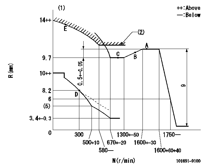
N:Pump speed
R:Rack position (mm)
(1)Beginning of damper spring operation: DL
(2)Excess fuel setting for starting: SXL
----------
DL=6.7-0.2mm SXL=10.2+0.2mm
----------
----------
DL=6.7-0.2mm SXL=10.2+0.2mm
----------
0000000901
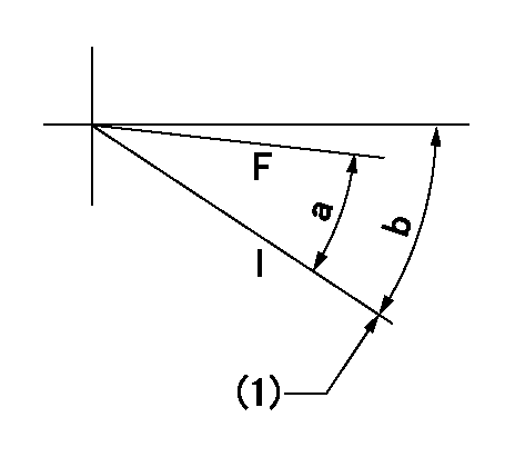
F:Full load
I:Idle
(1)Stopper bolt setting
----------
----------
a=25deg+-3deg b=30deg+-5deg
----------
----------
a=25deg+-3deg b=30deg+-5deg
Stop lever angle
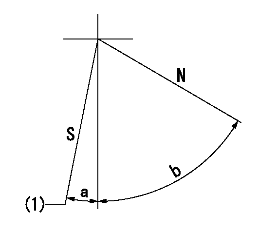
N:Pump normal
S:Stop the pump.
(1)Rack position = aa
----------
aa=0mm
----------
a=12deg+-5deg b=60deg+-5deg
----------
aa=0mm
----------
a=12deg+-5deg b=60deg+-5deg
Timing setting

(1)Pump vertical direction
(2)Position of gear mark 'P' at No 1 cylinder's beginning of injection
(3)-
(4)-
----------
----------
a=(50deg)
----------
----------
a=(50deg)
Information:
Start By:a. remove flywheel
Keep all parts clean from contaminants. Contaminants put into the system may cause rapid wear and shortened component life.
When a replacement of the rear seal is made, a replacement of the wear sleeve is to be made also. 1. Remove the crankshaft rear seal with tool (A). 2. Install tool (C) as shown.3. Install tool (B) between tool (C) and the wear sleeve. Turn tool (B) until the edge of the tool makes a flat place (crease) in the wear sleeve. Do this in two or more places until the wear sleeve in loose.4. Remove tool (C) and the wear sleeve by hand. The following steps are for the installation of the crankshaft rear seal and wear sleeve. 5. Install the crankshaft rear seal and wear sleeve with tooling (A) as follows:a. Put locator (1) in position on the crankshaft and install the three bolts that hold it in place.b. Put clean engine oil on the seal lip of seal (6) and on the outside diameter of wear sleeve (2).c. Install seal (6) on wear sleeve (2) from the end of the wear sleeve that has the bevel on the outside diameter. Make sure the lip of the seal is toward the inside of the engine and the bevel that is on the outside diameter of the wear sleeve is toward the outside of the engine when installed.d. Use 6V1541 Quick Cure Primer to clean the outside diameter of the crankshaft flange (3) and the inside diameter of wear sleeve (2).e. Put 9S3265 Retaining Compound on the outside diameter of crankshaft flange (3) and the inside diameter of wear sleeve (2). Make sure the lip of the seal is toward the inside of the engine and the outside diameter bevel of the wear sleeve is toward the outside of the engine.f. Put wear sleeve (2) with seal (6) on locator (1). Put installer (4) on locator (1) and install nut (5). Put lubrication on the face of the washer and the nut.g. Tighten nut (5) until installer (4) comes in contact with locator (1).h. Remove tooling (A) and check the wear sleeve and seal for correct installation.End By:a. install flywheel
Have questions with 101691-9100?
Group cross 101691-9100 ZEXEL
Nissan-Diesel
101691-9100
9 400 610 053
16700Z5515
INJECTION-PUMP ASSEMBLY
FD6
FD6