Information injection-pump assembly
BOSCH
9 400 615 972
9400615972
ZEXEL
101691-1850
1016911850
MITSUBISHI
ME018147
me018147
Rating:
Service parts 101691-1850 INJECTION-PUMP ASSEMBLY:
1.
_
6.
COUPLING PLATE
7.
COUPLING PLATE
8.
_
9.
_
11.
Nozzle and Holder
ME016540
12.
Open Pre:MPa(Kqf/cm2)
21.6(220)

15.
NOZZLE SET
Include in #1:
101691-1850
as INJECTION-PUMP ASSEMBLY
Include in #2:
104745-3550
as _
Cross reference number
BOSCH
9 400 615 972
9400615972
ZEXEL
101691-1850
1016911850
MITSUBISHI
ME018147
me018147
Zexel num
Bosch num
Firm num
Name
Calibration Data:
Adjustment conditions
Test oil
1404 Test oil ISO4113 or {SAEJ967d}
1404 Test oil ISO4113 or {SAEJ967d}
Test oil temperature
degC
40
40
45
Nozzle and nozzle holder
105780-8140
Bosch type code
EF8511/9A
Nozzle
105780-0000
Bosch type code
DN12SD12T
Nozzle holder
105780-2080
Bosch type code
EF8511/9
Opening pressure
MPa
17.2
Opening pressure
kgf/cm2
175
Injection pipe
Outer diameter - inner diameter - length (mm) mm 6-2-600
Outer diameter - inner diameter - length (mm) mm 6-2-600
Overflow valve
131424-5620
Overflow valve opening pressure
kPa
157
123
191
Overflow valve opening pressure
kgf/cm2
1.6
1.25
1.95
Tester oil delivery pressure
kPa
157
157
157
Tester oil delivery pressure
kgf/cm2
1.6
1.6
1.6
Direction of rotation (viewed from drive side)
Right R
Right R
Injection timing adjustment
Direction of rotation (viewed from drive side)
Right R
Right R
Injection order
1-5-3-6-
2-4
Pre-stroke
mm
3.5
3.45
3.55
Beginning of injection position
Drive side NO.1
Drive side NO.1
Difference between angles 1
Cal 1-5 deg. 60 59.5 60.5
Cal 1-5 deg. 60 59.5 60.5
Difference between angles 2
Cal 1-3 deg. 120 119.5 120.5
Cal 1-3 deg. 120 119.5 120.5
Difference between angles 3
Cal 1-6 deg. 180 179.5 180.5
Cal 1-6 deg. 180 179.5 180.5
Difference between angles 4
Cyl.1-2 deg. 240 239.5 240.5
Cyl.1-2 deg. 240 239.5 240.5
Difference between angles 5
Cal 1-4 deg. 300 299.5 300.5
Cal 1-4 deg. 300 299.5 300.5
Injection quantity adjustment
Adjusting point
A
Rack position
9.9
Pump speed
r/min
1500
1500
1500
Average injection quantity
mm3/st.
75.6
74.6
76.6
Max. variation between cylinders
%
0
-2.5
2.5
Basic
*
Fixing the lever
*
Injection quantity adjustment_02
Adjusting point
B
Rack position
7.4+-0.5
Pump speed
r/min
300
300
300
Average injection quantity
mm3/st.
7.5
6.2
8.8
Max. variation between cylinders
%
0
-14
14
Fixing the rack
*
Injection quantity adjustment_03
Adjusting point
C
Rack position
-
Pump speed
r/min
100
100
100
Average injection quantity
mm3/st.
66
66
71
Fixing the lever
*
Rack limit
*
Timer adjustment
Pump speed
r/min
1270--
Advance angle
deg.
0
0
0
Remarks
Start
Start
Timer adjustment_02
Pump speed
r/min
1200
Advance angle
deg.
0.5
Timer adjustment_03
Pump speed
r/min
1500
Advance angle
deg.
1.5
1
2
Timer adjustment_04
Pump speed
r/min
-
Advance angle
deg.
3
3
3
Remarks
Measure the actual speed, stop
Measure the actual speed, stop
Test data Ex:
Governor adjustment
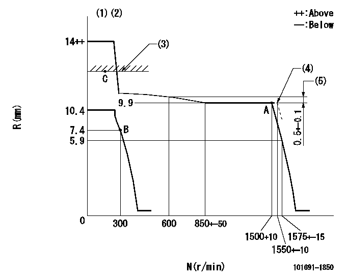
N:Pump speed
R:Rack position (mm)
(1)Target notch: K
(2)Supplied with torque spring not set.
(3)RACK LIMIT
(4)Setting at shipping
(5)Rack difference between N = N1 and N = N2
----------
K=8 N1=1500r/min N2=600r/min
----------
----------
K=8 N1=1500r/min N2=600r/min
----------
Speed control lever angle
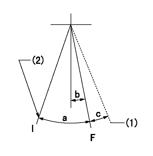
F:Full speed
I:Idle
(1)At shipping
(2)Stopper bolt setting
----------
----------
a=29deg+-5deg b=4deg+-5deg c=(2deg)
----------
----------
a=29deg+-5deg b=4deg+-5deg c=(2deg)
Stop lever angle

N:Pump normal
S:Stop the pump.
----------
----------
a=27deg+-5deg b=53deg+-5deg
----------
----------
a=27deg+-5deg b=53deg+-5deg
Timing setting

(1)Pump vertical direction
(2)Position of gear mark '3' at No 1 cylinder's beginning of injection
(3)B.T.D.C.: aa
(4)-
----------
aa=16deg
----------
a=(130deg)
----------
aa=16deg
----------
a=(130deg)
Information:
Measure wear of the cylinder bore at the top and bottom of piston ring travel.(1) Cylinder bore [standard, original size] ... 114.300 to 114.338 mm (4.5000 to 4.5015 in) The recommendation is made to make the cylinder bore the next size larger when the size of the bore is ... 114.452 mm (4.5060 in)Cylinder bore must be made the next size larger when the size of the bore is ... 114.529 mm (4.5090 in)Cylinder bore [0.51 mm (.020 in) larger than the original size] ... 114.821 0.013 mm (4.5205 .0005 in)The recommendation is made to make the cylinder bore the next size larger when the size of the bore is ... 114.960 mm (4.5260 in)Cylinder bore must be made the next size larger when the size of the bore is ... 115.037 mm (4.5290 in)Cylinder bore [1.02 mm (.040 in) larger than the original size] ... 115.329 0.013 mm (4.5405 .0005 in)Maximum permissible wear of cylinder bores (replacement of the cylinder block is necessary) ... 115.545 mm (4.5490 in)(2) Bore in block for camshaft bearing ... 67.374 0.013 mm (2.6525 .0005 in) Install camshaft bearings with the oil hole toward the top of the cylinder block.(3) Width of main bearing cap ... 166.624 0.018 mm (6.5600 .0007 in) Minimum permissible width of main bearing cap ... 166.573 mm (6.5580 in)Width of main bearing cap guide (in cylinder block) ... 166.599 0.013 mm (6.5590 .0005 in)(4) Bore in block for main bearing ... 94.171 0.013 mm (3.7075 .0005 in) Permissible amount of distortion in bore ... 94.13 to 94.21 mm (3.706 to 3.709 in) (5) Torque for bolts holding caps for main bearings: a. Put 2P2506 Thread Lubricant on bolt threads and washer face.b. Tighten all bolts in number sequence to ... 40 4 N m (30 3 lb ft)c. Put a mark on each bolt and cap.d. Tighten all bolts in number sequence from mark ... 120 5° (6) Dimension (new) from centerline of crankshaft bearing bore to bottom of block (pan rails) ... 95.250 0.038 mm (3.7500 .0015 in)(7) Dimension (new) from centerline of crankshaft bearing bore to top of block (top deck) ... 322.66 0.13 mm (12.703 .005 in)
There are holes in the bores for the main bearings, between the cylinders for piston cooling orifices. These holes must have orifices or plugs installed or low oil pressure will be the result.
If the base for the oil cooler is 357.2 mm (14.06 in) long the engine has piston cooling orifices installed. If the base for the oil cooler is 268.2 mm (10.56 in) long the engine has plugs installed.Piston cooling orifices were eliminated from 3208 truck engines effective with truck engine 2Z30692 with a rating of 150 KW (200 hp) @ 2000 rpm or 160 KW (215 hp) @ 2200 rpm. On earlier engines