Information injection-pump assembly
ZEXEL
101691-0990
1016910990
ISUZU
1156000610
1156000610

Rating:
Service parts 101691-0990 INJECTION-PUMP ASSEMBLY:
1.
_
4.
SUPPLY PUMP
7.
COUPLING PLATE
8.
_
9.
_
11.
Nozzle and Holder
9-15300-184-2
12.
Open Pre:MPa(Kqf/cm2)
9.8{100}
15.
NOZZLE SET
Include in #1:
101691-0990
as INJECTION-PUMP ASSEMBLY
Cross reference number
ZEXEL
101691-0990
1016910990
ISUZU
1156000610
1156000610
Zexel num
Bosch num
Firm num
Name
Calibration Data:
Adjustment conditions
Test oil
1404 Test oil ISO4113 or {SAEJ967d}
1404 Test oil ISO4113 or {SAEJ967d}
Test oil temperature
degC
40
40
45
Nozzle holder
105031-2480
Bosch type code
KB69SD273NP6
Opening pressure
MPa
9.8
Opening pressure
kgf/cm2
100
Injection pipe
Outer diameter - inner diameter - length (mm) mm 6-2-600
Outer diameter - inner diameter - length (mm) mm 6-2-600
Overflow valve
132424-0620
Overflow valve opening pressure
kPa
157
123
191
Overflow valve opening pressure
kgf/cm2
1.6
1.25
1.95
Tester oil delivery pressure
kPa
157
157
157
Tester oil delivery pressure
kgf/cm2
1.6
1.6
1.6
Direction of rotation (viewed from drive side)
Right R
Right R
Injection timing adjustment
Direction of rotation (viewed from drive side)
Right R
Right R
Injection order
1-4-2-6-
3-5
Pre-stroke
mm
2.2
2.15
2.25
Beginning of injection position
Drive side NO.1
Drive side NO.1
Difference between angles 1
Cal 1-4 deg. 60 59.5 60.5
Cal 1-4 deg. 60 59.5 60.5
Difference between angles 2
Cyl.1-2 deg. 120 119.5 120.5
Cyl.1-2 deg. 120 119.5 120.5
Difference between angles 3
Cal 1-6 deg. 180 179.5 180.5
Cal 1-6 deg. 180 179.5 180.5
Difference between angles 4
Cal 1-3 deg. 240 239.5 240.5
Cal 1-3 deg. 240 239.5 240.5
Difference between angles 5
Cal 1-5 deg. 300 299.5 300.5
Cal 1-5 deg. 300 299.5 300.5
Injection quantity adjustment
Adjusting point
A
Rack position
13
Pump speed
r/min
600
600
600
Average injection quantity
mm3/st.
117.5
115.2
119.8
Max. variation between cylinders
%
0
-2
2
Basic
*
Fixing the lever
*
Injection quantity adjustment_02
Adjusting point
B
Rack position
13
Pump speed
r/min
1000
1000
1000
Average injection quantity
mm3/st.
124
120.3
127.7
Max. variation between cylinders
%
0
-3
3
Fixing the lever
*
Injection quantity adjustment_03
Adjusting point
C
Rack position
6.5+-0.5
Pump speed
r/min
225
225
225
Average injection quantity
mm3/st.
17.5
15.2
19.8
Max. variation between cylinders
%
0
-13
13
Fixing the rack
*
Timer adjustment
Pump speed
r/min
400+-50
Advance angle
deg.
0
0
0
Remarks
Start
Start
Timer adjustment_02
Pump speed
r/min
600
Advance angle
deg.
0.6
0.1
1.1
Timer adjustment_03
Pump speed
r/min
900
Advance angle
deg.
1.4
0.9
1.9
Timer adjustment_04
Pump speed
r/min
1150
Advance angle
deg.
2
1.5
2.5
Remarks
Finish
Finish
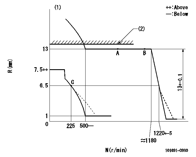
Test data Ex:
Governor adjustment

N:Pump speed
R:Rack position (mm)
(1)Beginning of damper spring operation: DL
(2)RACK LIMIT: RAL
----------
DL=6-0.2mm RAL=13+0.2mm
----------
----------
DL=6-0.2mm RAL=13+0.2mm
----------
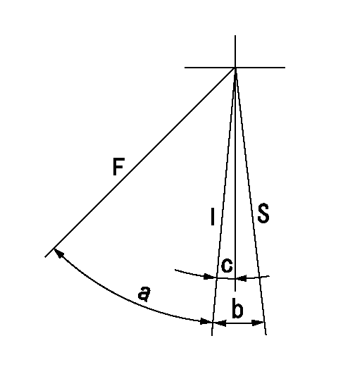
Speed control lever angle

F:Full speed
I:Idle
S:Stop
----------
----------
a=46deg+-2deg b=9deg+-2deg c=4deg+-5deg
----------
----------
a=46deg+-2deg b=9deg+-2deg c=4deg+-5deg
0000001501 MICRO SWITCH
Adjustment of the micro-switch
Adjust the bolt to obtain the following lever position when the micro-switch is ON.
(1)Speed N1
(2)Rack position Ra
----------
N1=275r/min Ra=6.5mm
----------
----------
N1=275r/min Ra=6.5mm
----------
Information:
ROCKER ARM SHAFT ASSEMBLY
1. Fuel return line (one each head). 2. Bolts and locks (four each head).4. Remove rocker arm shaft assembly (3). Remove push rods (4).
REMOVING ROCKER ARM SHAFT ASSEMBLY
3. Rocker arm shaft assembly (one each head). 4. Push rods (eight each head).Install Rocker Arm Shaft Assemblies
1. Lubricate the cam followers, push rods, and rocker arm shaft assembly with clean engine oil (SAE 30).2. Install push rods. Position the rocker arm shaft assembly on the cylinder head.3. Install the rocker arm shaft assembly retaining bolts and locks. Tighten bolts to 18 5 lb. ft. (2.5 0.7 mkg) and bend the locks.4. Install the fuel return line.5. Adjust the intake valve clearance to .015 in. (0.38 mm) and the exhaust valve clearance to .025 in. (0.64 mm).6. Install valve cover. Install valve cover retaining bolts and tighten bolts to 120 24 lb. in. (138 28 cm.kg).Disassemble Rocker Arm Shaft Assembly
1. Remove retaining bolts and locks from each end of rocker arm shaft assembly and disassemble the rocker arm shaft assembly.
ROCKER ARM SHAFT ASSEMBLY DISASSEMBLED
1. Rocker arm shaft. 2. Rivet. 3. Washers (eight). 4. Rocker arms (two per cylinder). 5. Adjusting screw. 6. Bracket. 7. Oil supply hole.Assemble Rocker Arm Shaft Assembly
1. The oil holes in shaft (1), arms (4) and bracket (6) must be clean and free of dirt or foreign material.2. Install adjusting screws (5) into rocker arms (4) so they extend .44 in. (11.2 mm) below arm. This will avoid forcing valves into piston crowns when rocker arm assembly is installed on cylinder head.
ROCKER ARM SHAFT ASSEMBLY
1. Rocker arm shaft. 2. Rivet. 3. Washers (eight). 4. Rocker arms (two per cylinder). 5. Adjusting screw. 6. Bracket. 7. Oil supply hole.3. Install arms (4) on shaft with washers (3) positioned as shown.4. Position shaft (1) and arms (4) into bracket (6) so screws (5) are on the same side of bracket (6) as oil supply hole (7). Rivet (2) must be on top when shaft (1) is positioned into bracket (6). Later rocker arm shaft assemblies have machined flats (8). The machined flats must be on top when shaft (1) is positioned into bracket (6).
LATER ROCKER ARM SHAFT ASSEMBLY
1. Rocker arm shaft. 6. Bracket. 8. Machined flats (four per shaft).
