Information injection-pump assembly
ZEXEL
101681-9570
1016819570

Rating:
Service parts 101681-9570 INJECTION-PUMP ASSEMBLY:
1.
_
6.
COUPLING PLATE
7.
COUPLING PLATE
8.
_
9.
_
10.
NOZZLE AND HOLDER ASSY
11.
Nozzle and Holder
12.
Open Pre:MPa(Kqf/cm2)
13.
NOZZLE-HOLDER
14.
NOZZLE
15.
NOZZLE SET
Include in #1:
101681-9570
as INJECTION-PUMP ASSEMBLY
Cross reference number
ZEXEL
101681-9570
1016819570
Zexel num
Bosch num
Firm num
Name
101681-9570
INJECTION-PUMP ASSEMBLY
6105Q *
6105Q *
Calibration Data:
Adjustment conditions
Test oil
1404 Test oil ISO4113 or {SAEJ967d}
1404 Test oil ISO4113 or {SAEJ967d}
Test oil temperature
degC
40
40
45
Nozzle and nozzle holder
105780-8140
Bosch type code
EF8511/9A
Nozzle
105780-0000
Bosch type code
DN12SD12T
Nozzle holder
105780-2080
Bosch type code
EF8511/9
Opening pressure
MPa
17.2
Opening pressure
kgf/cm2
175
Injection pipe
Outer diameter - inner diameter - length (mm) mm 6-2-600
Outer diameter - inner diameter - length (mm) mm 6-2-600
Tester oil delivery pressure
kPa
157
157
157
Tester oil delivery pressure
kgf/cm2
1.6
1.6
1.6
Direction of rotation (viewed from drive side)
Right R
Right R
Injection timing adjustment
Direction of rotation (viewed from drive side)
Right R
Right R
Injection order
1-5-3-6-
2-4
Pre-stroke
mm
2.2
2.15
2.25
Beginning of injection position
Drive side NO.1
Drive side NO.1
Difference between angles 1
Cal 1-5 deg. 60 59.5 60.5
Cal 1-5 deg. 60 59.5 60.5
Difference between angles 2
Cal 1-3 deg. 120 119.5 120.5
Cal 1-3 deg. 120 119.5 120.5
Difference between angles 3
Cal 1-6 deg. 180 179.5 180.5
Cal 1-6 deg. 180 179.5 180.5
Difference between angles 4
Cyl.1-2 deg. 240 239.5 240.5
Cyl.1-2 deg. 240 239.5 240.5
Difference between angles 5
Cal 1-4 deg. 300 299.5 300.5
Cal 1-4 deg. 300 299.5 300.5
Injection quantity adjustment
Adjusting point
A
Rack position
10
Pump speed
r/min
1400
1400
1400
Average injection quantity
mm3/st.
65
63
67
Max. variation between cylinders
%
0
-4
4
Basic
*
Fixing the lever
*
Injection quantity adjustment_02
Adjusting point
B
Rack position
7.5+-0.5
Pump speed
r/min
300
300
300
Average injection quantity
mm3/st.
10
8.5
11.5
Max. variation between cylinders
%
0
-15
15
Fixing the rack
*
Injection quantity adjustment_03
Adjusting point
C
Rack position
16+0.2
Pump speed
r/min
100
100
100
Average injection quantity
mm3/st.
100
100
Fixing the lever
*
Rack limit
*
Timer adjustment
Pump speed
r/min
750--
Advance angle
deg.
0
0
0
Remarks
Start
Start
Timer adjustment_02
Pump speed
r/min
700
Advance angle
deg.
0.5
Timer adjustment_03
Pump speed
r/min
1200
Advance angle
deg.
4
3.5
4.5
Remarks
Finish
Finish
Test data Ex:
Governor adjustment
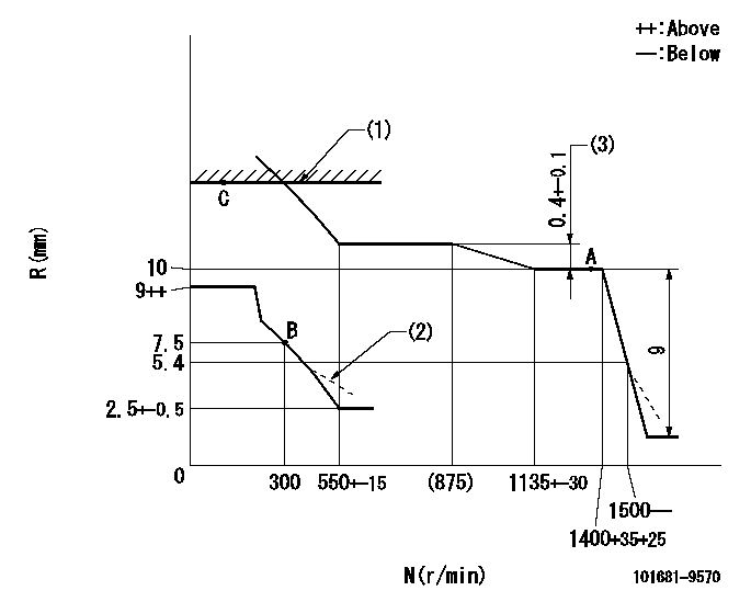
N:Pump speed
R:Rack position (mm)
(1)RACK LIMIT: RAL
(2)Damper spring setting: DL
(3)Rack difference between N = N1 and N = N2
----------
RAL=16+0.2mm DL=5.4-0.5mm N1=1400r/min N2=800r/min
----------
----------
RAL=16+0.2mm DL=5.4-0.5mm N1=1400r/min N2=800r/min
----------
0000000901

F:Full load
I:Idle
(1)Stopper bolt setting
----------
----------
a=10deg+-5deg b=27deg+-3deg
----------
----------
a=10deg+-5deg b=27deg+-3deg
Stop lever angle
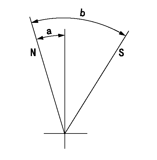
N:Pump normal
S:Stop the pump.
----------
----------
a=25deg+-5deg b=71deg+-5deg
----------
----------
a=25deg+-5deg b=71deg+-5deg
Timing setting

(1)Pump vertical direction
(2)Position of flange tooth's stamping at No. 1 cylinder's beginning of injection.
(3)-
(4)-
----------
----------
a=(50deg)
----------
----------
a=(50deg)
Information:
The 1674 Diesel Truck Engine is a 638 cu. in (10,5 ltr.) displacement, 4 stroke cycle, 6 cylinder turbocharged and aftercooled engine. This dual overhead cam engine with a 4 valve per cylinder design is made especially for highway trucks hauling big payloads. Serviceability is featured by spin-on throw away fuel filters, easy valve adjustment, replaceable cylinder liners and valve seats, and piston and rod removal from the top.Individual injection pumps, one for each cylinder, meter and pump fuel under high pressure to an injection valve and a precombustion chamber for each cylinder. An automatic variable timing device advances or retards fuel injection and is regulated by engine speed. The faster the engine turns the earlier the injection must take place before piston top center on the compression stroke.A hydro-mechanical governor controls the fuel injection pump out-put to maintain the engine RPM selected by the operator. A speed limiting device, in the governor, limits engine speed until engine oil pressure builds up.Inlet air, filtered by an air cleaner, is compressed by a turbocharger before entering the engine cylinders. The turbocharger is driven by the engine exhaust.There are four in-head valves (two inlet and two exhaust) for each cylinder. Two overhead camshafts, and forked rocker arm assemblies, are located in a housing on top of the cylinder head. The forked rocker arm assemblies act as a direct mechanical link between the lobes on the camshafts and the valve stems. The timing gears are located at the rear of the engine.Coolant for the engine is used to cool the engine lubricating oil. A full-flow temperature regulator, in the cylinder head at the front of the engine, provides for quick engine warm-up, and allows free circulation of coolant after operating temperature has been reached.Lubrication for the engine is supplied by a gear-type pump. The pump provides full pressure lubrication to the engine internal and external parts.The lubricating oil is both cooled and filtered. By-pass valves in the oil cooler assembly provide unrestricted flow of lubrication oil to the engine parts when oil viscosity is high or, if either the oil cooler or the oil filter element should become clogged.The starting system is direct electric and uses a 24 or 12 volt starting motor.Efficiency of emission controls and engine performance depends on adherence to proper operation and maintenance recommendations, and use of recommended fuels and lubrication oils. Major adjustments and repair should be entrusted to your authorized dealer. Follow the recommended maintenance schedule with special emphasis on fuel injection nozzles, air cleaner, fuel-air ratio control and high and low idle adjustment. Fuel-air ratio control and the high and low idle adjustments should be made by an authorized dealer.
Have questions with 101681-9570?
Group cross 101681-9570 ZEXEL
Nissan-Diesel
101681-9570
INJECTION-PUMP ASSEMBLY
6105Q
6105Q