Information injection-pump assembly
ZEXEL
101681-9520
1016819520

Rating:
Service parts 101681-9520 INJECTION-PUMP ASSEMBLY:
1.
_
7.
COUPLING PLATE
8.
_
9.
_
10.
NOZZLE AND HOLDER ASSY
11.
Nozzle and Holder
12.
Open Pre:MPa(Kqf/cm2)
13.
NOZZLE-HOLDER
14.
NOZZLE
15.
NOZZLE SET
Include in #1:
101681-9520
as INJECTION-PUMP ASSEMBLY
Cross reference number
ZEXEL
101681-9520
1016819520
Zexel num
Bosch num
Firm num
Name
101681-9520
INJECTION-PUMP ASSEMBLY
6105Q *
6105Q *
Calibration Data:
Adjustment conditions
Test oil
1404 Test oil ISO4113 or {SAEJ967d}
1404 Test oil ISO4113 or {SAEJ967d}
Test oil temperature
degC
40
40
45
Nozzle and nozzle holder
105780-8140
Bosch type code
EF8511/9A
Nozzle
105780-0000
Bosch type code
DN12SD12T
Nozzle holder
105780-2080
Bosch type code
EF8511/9
Opening pressure
MPa
17.2
Opening pressure
kgf/cm2
175
Injection pipe
Outer diameter - inner diameter - length (mm) mm 6-2-600
Outer diameter - inner diameter - length (mm) mm 6-2-600
Tester oil delivery pressure
kPa
157
157
157
Tester oil delivery pressure
kgf/cm2
1.6
1.6
1.6
Direction of rotation (viewed from drive side)
Right R
Right R
Injection timing adjustment
Direction of rotation (viewed from drive side)
Right R
Right R
Injection order
1-5-3-6-
2-4
Pre-stroke
mm
2.2
2.15
2.25
Beginning of injection position
Drive side NO.1
Drive side NO.1
Difference between angles 1
Cal 1-5 deg. 60 59.5 60.5
Cal 1-5 deg. 60 59.5 60.5
Difference between angles 2
Cal 1-3 deg. 120 119.5 120.5
Cal 1-3 deg. 120 119.5 120.5
Difference between angles 3
Cal 1-6 deg. 180 179.5 180.5
Cal 1-6 deg. 180 179.5 180.5
Difference between angles 4
Cyl.1-2 deg. 240 239.5 240.5
Cyl.1-2 deg. 240 239.5 240.5
Difference between angles 5
Cal 1-4 deg. 300 299.5 300.5
Cal 1-4 deg. 300 299.5 300.5
Injection quantity adjustment
Adjusting point
A
Rack position
10
Pump speed
r/min
1400
1400
1400
Average injection quantity
mm3/st.
65
63
67
Max. variation between cylinders
%
0
-4
4
Basic
*
Fixing the lever
*
Injection quantity adjustment_02
Adjusting point
B
Rack position
7.5+-0.5
Pump speed
r/min
300
300
300
Average injection quantity
mm3/st.
10
8.5
11.5
Max. variation between cylinders
%
0
-15
15
Fixing the rack
*
Timer adjustment
Pump speed
r/min
650--
Advance angle
deg.
0
0
0
Remarks
Start
Start
Timer adjustment_02
Pump speed
r/min
600
Advance angle
deg.
0.5
Timer adjustment_03
Pump speed
r/min
1000
Advance angle
deg.
1.4
0.9
1.9
Timer adjustment_04
Pump speed
r/min
1400
Advance angle
deg.
3
2.5
3.5
Remarks
Finish
Finish
Test data Ex:
Governor adjustment
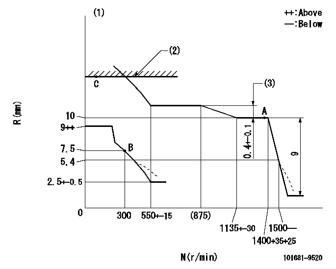
N:Pump speed
R:Rack position (mm)
(1)Damper spring setting: DL
(2)RACK LIMIT: RAL
(3)Rack difference between N = N1 and N = N2
----------
DL=5.4-0.5mm RAL=16+0.2mm N1=1400r/min N2=800r/min
----------
----------
DL=5.4-0.5mm RAL=16+0.2mm N1=1400r/min N2=800r/min
----------
0000000901

F:Full load
I:Idle
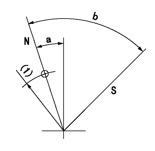
(1)Stopper bolt setting
----------
----------
a=10deg+-5deg b=27deg+-3deg
----------
----------
a=10deg+-5deg b=27deg+-3deg
Stop lever angle
N:Pump normal
S:Stop the pump.
(1)R = aa
----------
aa=30mm
----------
a=25deg+-5deg b=71deg+-5deg
----------
aa=30mm
----------
a=25deg+-5deg b=71deg+-5deg
Timing setting

(1)Pump vertical direction
(2)Coupling's key groove position at No 1 cylinder's beginning of injection
(3)-
(4)-
----------
----------
a=(40deg)
----------
----------
a=(40deg)
Information:
Illustration 1 g06022453
Typical example
(1) Existing fuel injection pump stop solenoid with red colored connection
(2) New fuel injection pump stop solenoid with cream colored connectionThere have been some isolated instances of issues with the existing fuel injection pump stop solenoid (1). The issues with the fuel injection pump stop solenoid have caused issues with starting the engine and fuel leaks.A new fuel injection pump stop solenoid (2) has been introduced. The improved fuel injection pump stop solenoid will offer better reliability and extended service life.The part number for the fuel injection pump stop solenoid has not changed.Follow step 1 through to step 7 for the correct procedure to replace the fuel injection pump stop solenoid.
Turn the battery disconnect switch to the OFF position.
Disconnect the electrical connection from the fuel injection pump stop solenoid.
Remove the existing fuel injection pump stop solenoid.
Install the new fuel injection pump stop solenoid. Tighten the fuel injection pump stop solenoid to a torque of 15 N m (133 lb in).
Remove the protective cap.
Connect the electrical connection to the fuel injection pump stop solenoid.
Turn the battery disconnect switch to the ON position.
Have questions with 101681-9520?
Group cross 101681-9520 ZEXEL
Nissan-Diesel
101681-9520
INJECTION-PUMP ASSEMBLY
6105Q
6105Q