Information injection-pump assembly
BOSCH
9 400 619 557
9400619557
ZEXEL
101681-9440
1016819440
Rating:
Service parts 101681-9440 INJECTION-PUMP ASSEMBLY:
1.
_

6.
COUPLING PLATE
7.
COUPLING PLATE
8.
_
9.
_
11.
Nozzle and Holder
12.
Open Pre:MPa(Kqf/cm2)
18.1{185}

15.
NOZZLE SET
Include in #1:
101681-9440
as INJECTION-PUMP ASSEMBLY
Include in #2:
104745-3100
as _
Cross reference number
BOSCH
9 400 619 557
9400619557
ZEXEL
101681-9440
1016819440
Zexel num
Bosch num
Firm num
Name
Calibration Data:
Adjustment conditions
Test oil
1404 Test oil ISO4113 or {SAEJ967d}
1404 Test oil ISO4113 or {SAEJ967d}
Test oil temperature
degC
40
40
45
Nozzle and nozzle holder
105780-8140
Bosch type code
EF8511/9A
Nozzle
105780-0000
Bosch type code
DN12SD12T
Nozzle holder
105780-2080
Bosch type code
EF8511/9
Opening pressure
MPa
17.2
Opening pressure
kgf/cm2
175
Injection pipe
Outer diameter - inner diameter - length (mm) mm 6-2-600
Outer diameter - inner diameter - length (mm) mm 6-2-600
Overflow valve
132424-0620
Overflow valve opening pressure
kPa
157
123
191
Overflow valve opening pressure
kgf/cm2
1.6
1.25
1.95
Tester oil delivery pressure
kPa
157
157
157
Tester oil delivery pressure
kgf/cm2
1.6
1.6
1.6
Direction of rotation (viewed from drive side)
Right R
Right R
Injection timing adjustment
Direction of rotation (viewed from drive side)
Right R
Right R
Injection order
1-5-3-6-
2-4
Pre-stroke
mm
2.2
2.15
2.25
Beginning of injection position
Drive side NO.1
Drive side NO.1
Difference between angles 1
Cal 1-5 deg. 60 59.5 60.5
Cal 1-5 deg. 60 59.5 60.5
Difference between angles 2
Cal 1-3 deg. 120 119.5 120.5
Cal 1-3 deg. 120 119.5 120.5
Difference between angles 3
Cal 1-6 deg. 180 179.5 180.5
Cal 1-6 deg. 180 179.5 180.5
Difference between angles 4
Cyl.1-2 deg. 240 239.5 240.5
Cyl.1-2 deg. 240 239.5 240.5
Difference between angles 5
Cal 1-4 deg. 300 299.5 300.5
Cal 1-4 deg. 300 299.5 300.5
Injection quantity adjustment
Adjusting point
A
Rack position
10.9
Pump speed
r/min
1500
1500
1500
Average injection quantity
mm3/st.
55.5
54
57
Max. variation between cylinders
%
0
-2.5
2.5
Basic
*
Fixing the lever
*
Injection quantity adjustment_02
Adjusting point
C
Rack position
7.7+-0.5
Pump speed
r/min
300
300
300
Average injection quantity
mm3/st.
9.4
8.1
10.7
Max. variation between cylinders
%
0
-14
14
Fixing the rack
*
Injection quantity adjustment_03
Adjusting point
D
Rack position
-
Pump speed
r/min
100
100
100
Average injection quantity
mm3/st.
60.5
60.5
Fixing the lever
*
Timer adjustment
Pump speed
r/min
550
Advance angle
deg.
0
0
0
Remarks
Start
Start
Timer adjustment_02
Pump speed
r/min
500
Advance angle
deg.
0.5
Timer adjustment_03
Pump speed
r/min
700
Advance angle
deg.
1
0.5
1.5
Timer adjustment_04
Pump speed
r/min
1100
Advance angle
deg.
2.7
2
3.4
Timer adjustment_05
Pump speed
r/min
1400
Advance angle
deg.
4.4
3.7
5.1
Timer adjustment_06
Pump speed
r/min
1500
Advance angle
deg.
4.8
4.1
5.5
Timer adjustment_07
Pump speed
r/min
-
Advance angle
deg.
6
6
6
Remarks
Measure the actual speed, stop
Measure the actual speed, stop
Test data Ex:
Governor adjustment
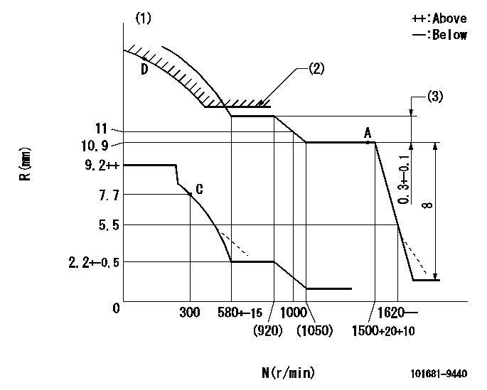
N:Pump speed
R:Rack position (mm)
(1)Beginning of damper spring operation: DL
(2)Excess fuel setting for starting: SXL
(3)Rack difference between N = N1 and N = N2
----------
DL=5.2-0.2mm SXL=12.1+0.2mm N1=1500r/min N2=900r/min
----------
----------
DL=5.2-0.2mm SXL=12.1+0.2mm N1=1500r/min N2=900r/min
----------
0000000901
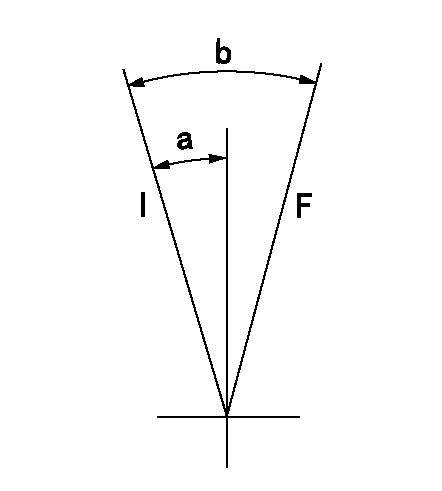
F:Full load
I:Idle
----------
----------
a=16deg+-5deg b=33deg+-3deg
----------
----------
a=16deg+-5deg b=33deg+-3deg
Stop lever angle
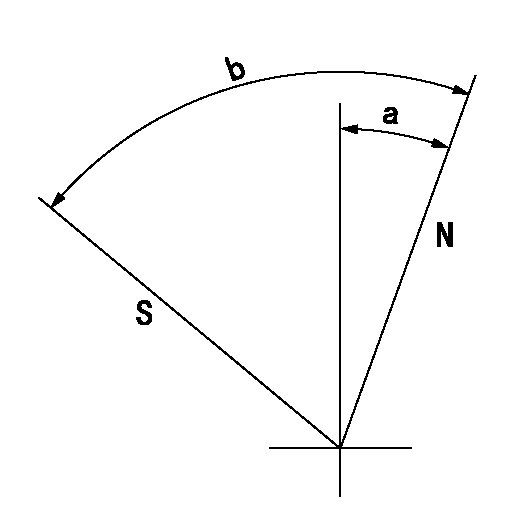
N:Pump normal
S:Stop the pump.
----------
----------
a=20deg+-5deg b=71deg+-5deg
----------
----------
a=20deg+-5deg b=71deg+-5deg
Timing setting

(1)Pump vertical direction
(2)Position of gear's standard threaded installation hole at No 1 cylinder's beginning of injection
(3)-
(4)-
----------
----------
a=(50deg)
----------
----------
a=(50deg)
Information:
Introduction
The valve housing may crack causing certain remanufactured fuel injectors to malfunction.Problem
Some remanufactured valve bodies on fuel injectors have been cracking under high pressure. This crack in the valve body can cause fuel to get into the engine oil.Solution
All 10R-0957 Injector Gp Fuel with serial number range 848368 to 850132 should be removed from the parts stock. 10R-0960 Injector Gp Fuel , 10R-0961 Injector Gp Fuel , 10R-0963 Injector Gp Fuel , and 10R-1268 Injector Gp Fuel with a serial number range from 188029 to 188914 should be removed from the parts stock. The above listed fuel injectors should be removed from the parts stock and the injectors should be held pending further instructions.