Information injection-pump assembly
ZEXEL
101681-9310
1016819310
NISSAN-DIESEL
16790Z5508
16790z5508

Rating:
Cross reference number
ZEXEL
101681-9310
1016819310
NISSAN-DIESEL
16790Z5508
16790z5508
Zexel num
Bosch num
Firm num
Name
Calibration Data:
Adjustment conditions
Test oil
1404 Test oil ISO4113 or {SAEJ967d}
1404 Test oil ISO4113 or {SAEJ967d}
Test oil temperature
degC
40
40
45
Nozzle and nozzle holder
105780-8140
Bosch type code
EF8511/9A
Nozzle
105780-0000
Bosch type code
DN12SD12T
Nozzle holder
105780-2080
Bosch type code
EF8511/9
Opening pressure
MPa
17.2
Opening pressure
kgf/cm2
175
Injection pipe
Outer diameter - inner diameter - length (mm) mm 6-2-600
Outer diameter - inner diameter - length (mm) mm 6-2-600
Overflow valve opening pressure
kPa
157
123
191
Overflow valve opening pressure
kgf/cm2
1.6
1.25
1.95
Tester oil delivery pressure
kPa
157
157
157
Tester oil delivery pressure
kgf/cm2
1.6
1.6
1.6
Direction of rotation (viewed from drive side)
Right R
Right R
Injection timing adjustment
Direction of rotation (viewed from drive side)
Right R
Right R
Injection order
1-4-2-6-
3-5
Pre-stroke
mm
2.4
2.35
2.45
Beginning of injection position
Drive side NO.1
Drive side NO.1
Difference between angles 1
Cal 1-4 deg. 60 59.5 60.5
Cal 1-4 deg. 60 59.5 60.5
Difference between angles 2
Cyl.1-2 deg. 120 119.5 120.5
Cyl.1-2 deg. 120 119.5 120.5
Difference between angles 3
Cal 1-6 deg. 180 179.5 180.5
Cal 1-6 deg. 180 179.5 180.5
Difference between angles 4
Cal 1-3 deg. 240 239.5 240.5
Cal 1-3 deg. 240 239.5 240.5
Difference between angles 5
Cal 1-5 deg. 300 299.5 300.5
Cal 1-5 deg. 300 299.5 300.5
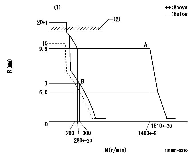
Injection quantity adjustment
Adjusting point
A
Rack position
9.9
Pump speed
r/min
1350
1350
1350
Average injection quantity
mm3/st.
75.2
73.8
76.6
Max. variation between cylinders
%
0
-2
2
Basic
*
Fixing the lever
*
Injection quantity adjustment_02
Adjusting point
B
Rack position
7+-0.5
Pump speed
r/min
300
300
300
Average injection quantity
mm3/st.
14.6
12.8
16.4
Max. variation between cylinders
%
0
-15
15
Fixing the rack
*
Timer adjustment
Pump speed
r/min
700--
Advance angle
deg.
0
0
0
Remarks
Start
Start
Timer adjustment_02
Pump speed
r/min
650
Advance angle
deg.
0.5
Timer adjustment_03
Pump speed
r/min
1350
Advance angle
deg.
2.3
1.8
2.8
Timer adjustment_04
Pump speed
r/min
1400
Advance angle
deg.
2.5
2
3
Timer adjustment_05
Pump speed
r/min
-
Advance angle
deg.
3
2.5
3.5
Remarks
Measure the actual speed, stop
Measure the actual speed, stop
Test data Ex:
Governor adjustment
N:Pump speed
R:Rack position (mm)
(1)Target notch: K
(2)RACK LIMIT: RAL
----------
K=15 RAL=13.9+-0.1mm
----------
----------
K=15 RAL=13.9+-0.1mm
----------
Speed control lever angle
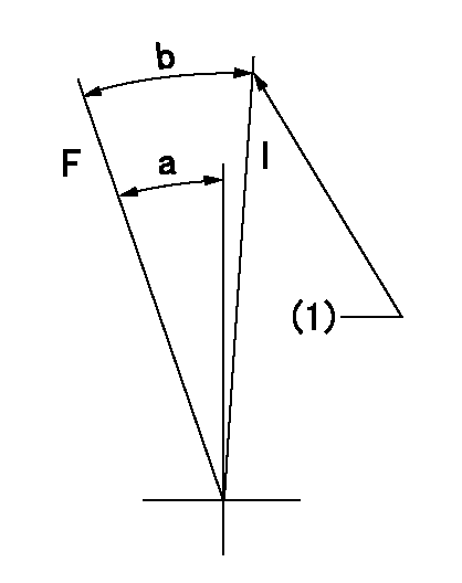
F:Full speed
I:Idle
(1)Stopper bolt setting
----------
----------
a=20deg+-5deg b=26deg+-5deg
----------
----------
a=20deg+-5deg b=26deg+-5deg
Stop lever angle

N:Pump normal
S:Stop the pump.
----------
----------
a=19deg+-5deg b=53deg+-5deg
----------
----------
a=19deg+-5deg b=53deg+-5deg
Timing setting

(1)Pump vertical direction
(2)Position of gear mark 'P' at No 1 cylinder's beginning of injection
(3)-
(4)-
----------
----------
a=(50deg)
----------
----------
a=(50deg)
Information:
Table 15
CDL Diagnostic
Sensor Description DTC CID FMI Harness Pin Number Harness Connector
Fuel Supply Flow Rotor Speed Sensor 1 4515 10 and 14 J1-6 A-C2
Fuel Supply Flow Rotor Speed Sensor 2 4516 8 J1-52 A-C3
Fuel Return Flow Rotor Speed Sensor 1 4517 10 and 14 J1-61 C-C2
Fuel Return Flow Rotor Speed Sensor 2 4518 8 J1-63 C-C3 If the fuel volume speed sensor detects an abnormal rate of change, a diagnostic of FMI 10, "Abnormal Rate of Change", will be reported on the SAE J1939 data link and the CDL data link for the errant sensor. An "Abnormal Rate of Change" will be detected when the measured frequency is greater than the maximum flow rate for which the transducer is rated.If the fuel volume speed sensor detects an abnormal frequency, pulse width or period, a diagnostic of FMI 8, "Abnormal Frequency, Pulse Width or Period", will be reported on the SAE J1939 data link and the CDL data link for the errant sensor. This indicates a loose or pinched wire or an errant speed sensor. An abnormal frequency, pulse width, or period will be detected if the frequency reading indicates that the transducer has been installed backwards.If the fuel volume speed sensor outputs a flow rate of 160 pps or more, a diagnostic with FMI 14 will be reported on the SAE J1939 data link and the CDL. This indicates that the flow rate through the transducer is approaching the maximum flow rate.Temperature Sensor Diagnostic Indicators
If a temperature sensor fails, the ECM raises a diagnostic message and sends it on the main SAE J1939 data link and the CDL bus.
Table 16
Sensor Description SAE J1939 SPN CDL DTC CID Harness Pin Number Harness Connector
Fuel Flow Supply Temperature Sensor 2775 4519 J1-36 A-C4
Fuel Flow Supply Temperature Sensor 2776 1929 J1-37 C-C4 If a diagnostic of FMI 3, Voltage Above Normal, is reported on the SAE J1939 data link or the CDL data link for the errant sensor, this indicates possible short to battery indicating a broken wire or defective sensor.If a diagnostic of FMI 4, Voltage Below Normal, is reported on the SAE J1939 data link or the CDL data link for the errant sensor, this indicates possible short to ground indicating a pinched wire or defective sensor.Data Retention
The system is designed to monitor the fuel consumed by the engine, irrespective of time. If either transducer is replaced, the ECM will not reset the fuel volume values.Replacing Failed Parts
The fuel volume transducer is a precision device. If the transducer experiences a failure in one of the sensors, the specific sensor can be replaced without impacting the calibration of the device.Replacement part numbers are as follows:
Table 17
Replacement Parts
Part Description Low Flow Rate System High Flow Rate System
Speed Sensor 384-3887 Speed Sensor Gp 384-3887 Speed Sensor Gp
Speed Sensor O-ring
Temperature Sensor 191-6587 Temperature Sensor Gp 238-0112 Temperature Sensor Gp
Temperature Sensor O-ring 214-7568 O-Ring Seal 214-7568 O-Ring Seal
Transducer 434-5030 Flow Meter Gp 434-5040 Flow Meter Gp Replacing