Information injection-pump assembly
ZEXEL
101681-9300
1016819300
NISSAN-DIESEL
16713Z5561
16713z5561

Rating:
Cross reference number
ZEXEL
101681-9300
1016819300
NISSAN-DIESEL
16713Z5561
16713z5561
Zexel num
Bosch num
Firm num
Name
101681-9300
16713Z5561 NISSAN-DIESEL
INJECTION-PUMP ASSEMBLY
FD6T * K
FD6T * K
Calibration Data:
Adjustment conditions
Test oil
1404 Test oil ISO4113 or {SAEJ967d}
1404 Test oil ISO4113 or {SAEJ967d}
Test oil temperature
degC
40
40
45
Nozzle and nozzle holder
105780-8140
Bosch type code
EF8511/9A
Nozzle
105780-0000
Bosch type code
DN12SD12T
Nozzle holder
105780-2080
Bosch type code
EF8511/9
Opening pressure
MPa
17.2
Opening pressure
kgf/cm2
175
Injection pipe
Outer diameter - inner diameter - length (mm) mm 6-2-600
Outer diameter - inner diameter - length (mm) mm 6-2-600
Overflow valve
132424-0620
Overflow valve opening pressure
kPa
157
123
191
Overflow valve opening pressure
kgf/cm2
1.6
1.25
1.95
Tester oil delivery pressure
kPa
157
157
157
Tester oil delivery pressure
kgf/cm2
1.6
1.6
1.6
Direction of rotation (viewed from drive side)
Right R
Right R
Injection timing adjustment
Direction of rotation (viewed from drive side)
Right R
Right R
Injection order
1-4-2-6-
3-5
Pre-stroke
mm
2.4
2.35
2.45
Beginning of injection position
Drive side NO.1
Drive side NO.1
Difference between angles 1
Cal 1-4 deg. 60 59.5 60.5
Cal 1-4 deg. 60 59.5 60.5
Difference between angles 2
Cyl.1-2 deg. 120 119.5 120.5
Cyl.1-2 deg. 120 119.5 120.5
Difference between angles 3
Cal 1-6 deg. 180 179.5 180.5
Cal 1-6 deg. 180 179.5 180.5
Difference between angles 4
Cal 1-3 deg. 240 239.5 240.5
Cal 1-3 deg. 240 239.5 240.5
Difference between angles 5
Cal 1-5 deg. 300 299.5 300.5
Cal 1-5 deg. 300 299.5 300.5
Injection quantity adjustment
Adjusting point
A
Rack position
10.8
Pump speed
r/min
1000
1000
1000
Average injection quantity
mm3/st.
74.2
72.6
75.8
Max. variation between cylinders
%
0
-2
2
Basic
*
Fixing the lever
*
Boost pressure
kPa
60
60
Boost pressure
mmHg
450
450
Injection quantity adjustment_02
Adjusting point
B
Rack position
7.5+-0.5
Pump speed
r/min
300
300
300
Average injection quantity
mm3/st.
13.9
12.1
15.7
Max. variation between cylinders
%
0
-12
12
Fixing the rack
*
Boost pressure
kPa
0
0
0
Boost pressure
mmHg
0
0
0
Boost compensator adjustment
Pump speed
r/min
1000
1000
1000
Rack position
9.8
Boost pressure
kPa
22.7
22.7
25.4
Boost pressure
mmHg
170
170
190
Boost compensator adjustment_02
Pump speed
r/min
1000
1000
1000
Rack position
10.8
Boost pressure
kPa
49.3
49.3
49.3
Boost pressure
mmHg
370
370
370
Timer adjustment
Pump speed
r/min
700
Advance angle
deg.
0.5
Timer adjustment_02
Pump speed
r/min
900
Advance angle
deg.
1
Timer adjustment_03
Pump speed
r/min
1100
Advance angle
deg.
1.1
0.6
1.6
Timer adjustment_04
Pump speed
r/min
1300
Advance angle
deg.
1.8
1.3
2.3
Timer adjustment_05
Pump speed
r/min
1600
Advance angle
deg.
3
2.5
3.5
Remarks
Finish
Finish
Test data Ex:
Governor adjustment
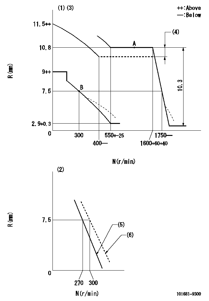
N:Pump speed
R:Rack position (mm)
(1)Adjust with speed control lever at full position (minimum-maximum speed specification)
(2)Adjust with the load control lever in the full position (variable speed specification).
(3)Beginning of damper spring operation: DL
(4)Boost compensator stroke: BCL (N = N1)
(5)Set the idle spring.
(6)Main spring setting
----------
DL=6.5-0.2mm BCL=1+-0.1mm N1=1000r/min
----------
----------
DL=6.5-0.2mm BCL=1+-0.1mm N1=1000r/min
----------
Speed control lever angle
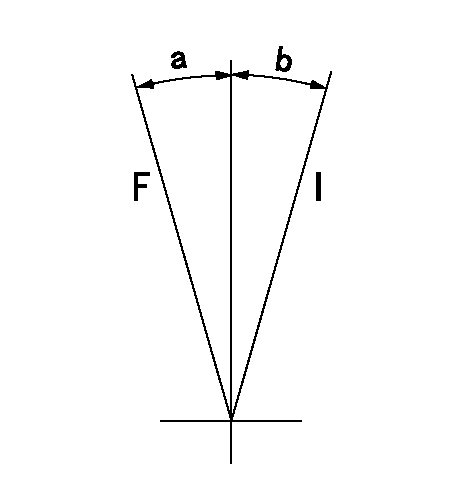
F:Full speed
I:Idle
----------
----------
a=20deg+-5deg b=9deg+-5deg
----------
----------
a=20deg+-5deg b=9deg+-5deg
0000000901

F:Full load
I:Idle
(1)Stopper bolt setting
----------
----------
a=15deg+-5deg b=28.5deg+-3deg
----------
----------
a=15deg+-5deg b=28.5deg+-3deg
Stop lever angle

N:Pump normal
S:Stop the pump.
----------
----------
a=21deg+-5deg b=47deg+-5deg
----------
----------
a=21deg+-5deg b=47deg+-5deg
Timing setting

(1)Pump vertical direction
(2)Position of gear mark 'P' at No 1 cylinder's beginning of injection
(3)-
(4)-
----------
----------
a=(50deg)
----------
----------
a=(50deg)
Information:
Introduction
Procedure to prevent injector Plunger Spring failure due to inadequate fuel system priming.
The low-pressure fuel system must be primed after injector replacement or other repair to the low-pressure fuel system circuit which may allow air to enter the system.
Inadequate priming can result in air being present in the low-pressure fuel system and inside the injectors.
Attempting to start the engine without adequate priming may result in an early hour failure of the injector plunger spring.
Follow the procedure below to prevent injector failure due to inadequate priming.
DO NOT START THE ENGINE WITHOUT PRIMING THE FUEL SYSTEM
Illustration 1 g03735591
Damaged plunger spring due to improper fuel system primingFuel System Priming Procedure:
Disconnect the injector harness at the valve cover.
Use the hand primer to fill the fuel system. Pump until the hand primer becomes too hard to depress by hand.
Crank the engine 3 times for 15 seconds each. Reapply the hand primer after each cranking cycle.
Once the hand primer remains hard to depress after the 15 second crank, reconnect the injector harness and start the engine.
Clear any related fault codes (ET) that were logged while cranking the engine with the injector harness disconnected.
Illustration 2 g03736011
Have questions with 101681-9300?
Group cross 101681-9300 ZEXEL
Nissan-Diesel
101681-9300
16713Z5561
INJECTION-PUMP ASSEMBLY
FD6T
FD6T