Information injection-pump assembly
ZEXEL
101681-9180
1016819180
NISSAN-DIESEL
16713Z5503
16713z5503

Rating:
Service parts 101681-9180 INJECTION-PUMP ASSEMBLY:
1.
_
6.
COUPLING PLATE
7.
COUPLING PLATE
8.
_
9.
_
11.
Nozzle and Holder
16600-Z5508
12.
Open Pre:MPa(Kqf/cm2)
21.6{220}

15.
NOZZLE SET
Include in #1:
101681-9180
as INJECTION-PUMP ASSEMBLY
Include in #2:
104740-8720
as _
Cross reference number
ZEXEL
101681-9180
1016819180
NISSAN-DIESEL
16713Z5503
16713z5503
Zexel num
Bosch num
Firm num
Name
101681-9180
16713Z5503 NISSAN-DIESEL
INJECTION-PUMP ASSEMBLY
FD6T * K
FD6T * K
Calibration Data:
Adjustment conditions
Test oil
1404 Test oil ISO4113 or {SAEJ967d}
1404 Test oil ISO4113 or {SAEJ967d}
Test oil temperature
degC
40
40
45
Nozzle and nozzle holder
105780-8140
Bosch type code
EF8511/9A
Nozzle
105780-0000
Bosch type code
DN12SD12T
Nozzle holder
105780-2080
Bosch type code
EF8511/9
Opening pressure
MPa
17.2
Opening pressure
kgf/cm2
175
Injection pipe
Outer diameter - inner diameter - length (mm) mm 6-2-600
Outer diameter - inner diameter - length (mm) mm 6-2-600
Overflow valve
132424-0620
Overflow valve opening pressure
kPa
157
123
191
Overflow valve opening pressure
kgf/cm2
1.6
1.25
1.95
Tester oil delivery pressure
kPa
157
157
157
Tester oil delivery pressure
kgf/cm2
1.6
1.6
1.6
Direction of rotation (viewed from drive side)
Right R
Right R
Injection timing adjustment
Direction of rotation (viewed from drive side)
Right R
Right R
Injection order
1-4-2-6-
3-5
Pre-stroke
mm
2.4
2.35
2.45
Beginning of injection position
Drive side NO.1
Drive side NO.1
Difference between angles 1
Cal 1-4 deg. 60 59.5 60.5
Cal 1-4 deg. 60 59.5 60.5
Difference between angles 2
Cyl.1-2 deg. 120 119.5 120.5
Cyl.1-2 deg. 120 119.5 120.5
Difference between angles 3
Cal 1-6 deg. 180 179.5 180.5
Cal 1-6 deg. 180 179.5 180.5
Difference between angles 4
Cal 1-3 deg. 240 239.5 240.5
Cal 1-3 deg. 240 239.5 240.5
Difference between angles 5
Cal 1-5 deg. 300 299.5 300.5
Cal 1-5 deg. 300 299.5 300.5
Injection quantity adjustment
Adjusting point
A
Rack position
11.7
Pump speed
r/min
1000
1000
1000
Average injection quantity
mm3/st.
68.8
67.2
70.4
Max. variation between cylinders
%
0
-2.5
2.5
Basic
*
Fixing the rack
*
Standard for adjustment of the maximum variation between cylinders
*
Injection quantity adjustment_02
Adjusting point
D
Rack position
8.5+-0.5
Pump speed
r/min
300
300
300
Average injection quantity
mm3/st.
15
13.2
16.8
Max. variation between cylinders
%
0
-12
12
Fixing the rack
*
Standard for adjustment of the maximum variation between cylinders
*
Injection quantity adjustment_03
Adjusting point
A
Rack position
R1(11.7)
Pump speed
r/min
1000
1000
1000
Average injection quantity
mm3/st.
68.8
67.2
70.4
Basic
*
Fixing the lever
*
Injection quantity adjustment_04
Adjusting point
B
Rack position
11.95+-0
.5
Pump speed
r/min
1600
1600
1600
Average injection quantity
mm3/st.
74.1
71.8
76.4
Fixing the lever
*
Injection quantity adjustment_05
Adjusting point
C
Rack position
10.45+-0
.5
Pump speed
r/min
500
500
500
Average injection quantity
mm3/st.
43.1
41.1
45.1
Fixing the lever
*
Injection quantity adjustment_06
Adjusting point
D
Rack position
8.5+-0.5
Pump speed
r/min
300
300
300
Average injection quantity
mm3/st.
15
13.2
16.8
Fixing the lever
*
Timer adjustment
Pump speed
r/min
400+-50
Advance angle
deg.
0
0
0
Remarks
Start
Start
Timer adjustment_02
Pump speed
r/min
1000
Advance angle
deg.
1.5
1
2
Timer adjustment_03
Pump speed
r/min
1600
Advance angle
deg.
3
2.5
3.5
Remarks
Finish
Finish
Test data Ex:
Governor adjustment
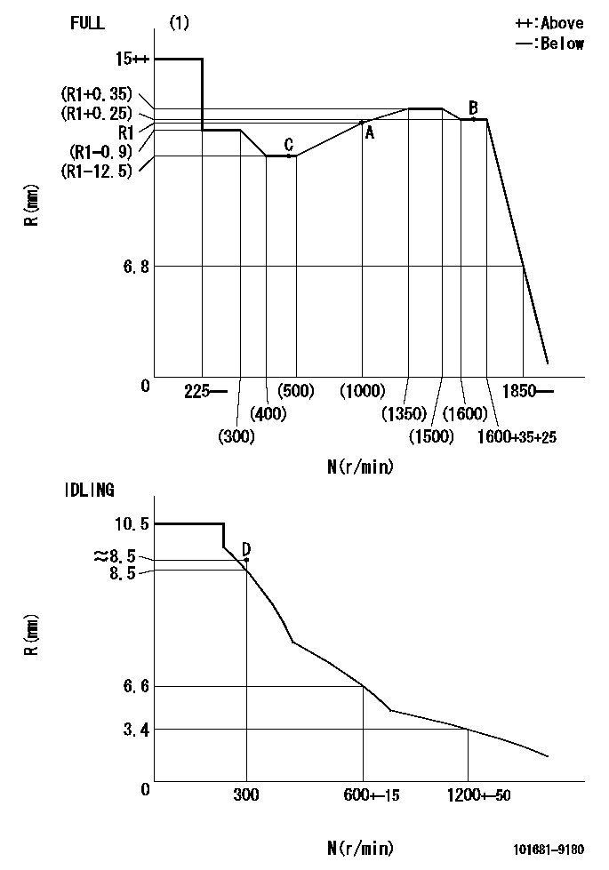
N:Pump speed
R:Rack position (mm)
(1)Torque cam stamping: T1
----------
T1=28
----------
----------
T1=28
----------
Speed control lever angle

F:Full speed
I:Idle
(1)Stopper bolt setting
----------
----------
a=30.5deg+-5deg b=45.5deg+-3deg
----------
----------
a=30.5deg+-5deg b=45.5deg+-3deg
Stop lever angle

N:Pump normal
S:Stop the pump.
----------
----------
a=40deg+-5deg b=40deg+-5deg
----------
----------
a=40deg+-5deg b=40deg+-5deg
Timing setting

(1)Pump vertical direction
(2)Position of gear mark 'P' at No 1 cylinder's beginning of injection
(3)-
(4)-
----------
----------
a=(50deg)
----------
----------
a=(50deg)
Information:
Table 2
Specifications for Pressure Loss
Direct Injection Fuel Systems
Nozzle pressure must not drop below a gauge reading of
3450 kPa (500 psi) during a 5 second time interval.
Nozzle pressure must drop below a gauge reading of
1380 kPa (200 psi) after an additional 25 second time interval. (1)
( 1 ) A gauge reading of 0 kPa (0 psi) is acceptable after the first 5 second time interval has elapsed.
Illustration 3 g00923167
If the fuel nozzle is not within specifications, stop the test and do not use the fuel nozzle.Valve Opening Pressure Test
Slowly increase the pressure until fluid begins to flow from the tip of the fuel nozzle. Record this pressure as the VOP of the fuel nozzle.
Compare the test results to the specifications for the type of fuel nozzle that is being tested. Refer to Table 3, or Table 4.For precombustion chamber fuel systems, use these specifications:
Table 3
Specifications for Valve Opening Pressure
Precombustion Chamber Fuel Systems
2760 to 5170 kPa (400 to 750 psi)
Illustration 4 g00934108
If the VOP is not within specifications, stop the test and do not use the fuel nozzle.For direct injection fuel systems, use these specifications:
Table 4
Specifications for Valve Opening Pressure
Direct Injection Fuel Systems
16500 to 21400 kPa (2400 to 3100 psi)
Illustration 5 g00923174
If the VOP is not within specifications, stop the test and do not use the fuel nozzle.Tip Leakage Test (Direct Injection Fuel Systems)
Note: Fuel nozzles for precombustion chamber fuel systems can not be tested for tip leakage accurately. Do not perform this test on fuel nozzles for a precombustion
Have questions with 101681-9180?
Group cross 101681-9180 ZEXEL
Nissan-Diesel
Nissan-Diesel
101681-9180
16713Z5503
INJECTION-PUMP ASSEMBLY
FD6T
FD6T