Information injection-pump assembly
BOSCH
9 400 615 953
9400615953
ZEXEL
101672-0210
1016720210
Rating:
Service parts 101672-0210 INJECTION-PUMP ASSEMBLY:
1.
_
5.
AUTOM. ADVANCE MECHANIS
6.
COUPLING PLATE
8.
_
9.
_
11.
Nozzle and Holder
5-15300-097-0
12.
Open Pre:MPa(Kqf/cm2)
11.8{120}

15.
NOZZLE SET
Include in #1:
101672-0210
as INJECTION-PUMP ASSEMBLY
Cross reference number
BOSCH
9 400 615 953
9400615953
ZEXEL
101672-0210
1016720210
Zexel num
Bosch num
Firm num
Name
101672-0210
9 400 615 953
INJECTION-PUMP ASSEMBLY
D500 * 14BE PE6A PE
D500 * 14BE PE6A PE
101672-0210
9 400 615 953
1156007904 ISUZU
INJECTION-PUMP ASSEMBLY
D500 * 14BE PE6A PE
D500 * 14BE PE6A PE
Calibration Data:
Adjustment conditions
Test oil
1404 Test oil ISO4113 or {SAEJ967d}
1404 Test oil ISO4113 or {SAEJ967d}
Test oil temperature
degC
40
40
45
Nozzle and nozzle holder
105780-8140
Bosch type code
EF8511/9A
Nozzle
105780-0000
Bosch type code
DN12SD12T
Nozzle holder
105780-2080
Bosch type code
EF8511/9
Opening pressure
MPa
17.2
Opening pressure
kgf/cm2
175
Injection pipe
Outer diameter - inner diameter - length (mm) mm 6-2-600
Outer diameter - inner diameter - length (mm) mm 6-2-600
Tester oil delivery pressure
kPa
157
157
157
Tester oil delivery pressure
kgf/cm2
1.6
1.6
1.6
Direction of rotation (viewed from drive side)
Right R
Right R
Injection timing adjustment
Direction of rotation (viewed from drive side)
Right R
Right R
Injection order
1-5-3-6-
2-4
Pre-stroke
mm
2.2
2.15
2.25
Beginning of injection position
Drive side NO.1
Drive side NO.1
Difference between angles 1
Cal 1-5 deg. 60 59.5 60.5
Cal 1-5 deg. 60 59.5 60.5
Difference between angles 2
Cal 1-3 deg. 120 119.5 120.5
Cal 1-3 deg. 120 119.5 120.5
Difference between angles 3
Cal 1-6 deg. 180 179.5 180.5
Cal 1-6 deg. 180 179.5 180.5
Difference between angles 4
Cyl.1-2 deg. 240 239.5 240.5
Cyl.1-2 deg. 240 239.5 240.5
Difference between angles 5
Cal 1-4 deg. 300 299.5 300.5
Cal 1-4 deg. 300 299.5 300.5
Injection quantity adjustment
Adjusting point
A
Rack position
11.1
Pump speed
r/min
800
800
800
Average injection quantity
mm3/st.
45.2
43.7
46.7
Max. variation between cylinders
%
0
-2
2
Basic
*
Fixing the lever
*
Injection quantity adjustment_02
Adjusting point
B
Rack position
10.2
Pump speed
r/min
1050
1050
1050
Average injection quantity
mm3/st.
43.5
41
46
Max. variation between cylinders
%
0
-4
4
Fixing the lever
*
Injection quantity adjustment_03
Adjusting point
C
Rack position
8.3+-0.5
Pump speed
r/min
275
275
275
Average injection quantity
mm3/st.
9.4
7.9
10.9
Max. variation between cylinders
%
0
-10
10
Fixing the rack
*
Remarks
Adjust only variation between cylinders; adjust governor according to governor specifications.
Adjust only variation between cylinders; adjust governor according to governor specifications.
Test data Ex:
Governor adjustment
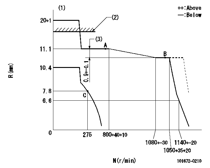
N:Pump speed
R:Rack position (mm)
(1)Target notch: K
(2)RACK LIMIT: RAL
(3)Torque control stroke
----------
K=6 RAL=(17.5)mm
----------
----------
K=6 RAL=(17.5)mm
----------
Speed control lever angle
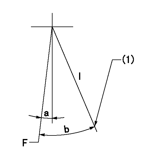
F:Full speed
I:Idle
(1)Stopper bolt setting
----------
----------
a=2deg+-5deg b=25.5deg+-5deg
----------
----------
a=2deg+-5deg b=25.5deg+-5deg
Stop lever angle
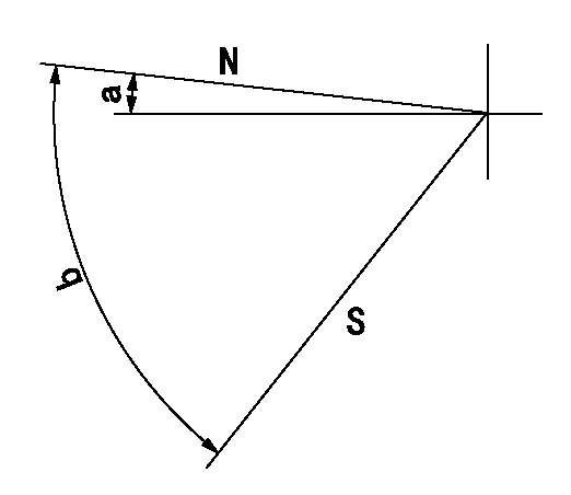
N:Pump normal
S:Stop the pump.
----------
----------
a=4.5deg+-5deg b=53deg+-5deg
----------
----------
a=4.5deg+-5deg b=53deg+-5deg
Timing setting

(1)Pump vertical direction
(2)Position of gear mark 'CC' at No 1 cylinder's beginning of injection
(3)B.T.D.C.: aa
(4)-
----------
aa=15deg
----------
a=(100deg)
----------
aa=15deg
----------
a=(100deg)
Information:
TECHNICAL INFORMATION BULLETIN JAN. 15th, 2003
EXCAVATORS
WHEEL LOADERS
ENGINES 322C: (EMR, MAR);
325C: (CRB, CSJ, JLC, JLD, DTF)
950G II: (AYL, AYB);
962G II: (AYE, BAB)
3126B: (BMA)
Component Code(s) 1408SUBJECT: A NEW INJECTION ACTUATION PRESSURE CONTROL VALVE CONNECTOR INCREASES ENGINE OPERATION
PROBLEM:
The injection actuation pressure (IAP) control valve connector may have been assembled incorrectly on some 3126B engine harnesses. This can lead to intermittent engine operation or can cause the engine to stop.
SOLUTION:
If your machine exhibits symptoms of intermittent engine operation or abruptly stopping, the IAP control valve connector should be disconnected from the machine, examined for solenoid contact problems and re-installed using a correct procedure.
Procedure for installing the IAP control valve connector
This procedure will describe how to properly install the 232-4367 Harness.
Required Parts
Qty Part Number Description
1 232-4367 Harness
Procure the part that is listed in the table.
Illustration 1. Left Side of a 3126B Engine on a D6N.
(1) IAP Control Valve
(2) IAP Control Valve Connector
Note: Illustration 1 is from a D6N that is equipped with a 3126B for photographical purposes. The location of the IAP Control Valve is the same for your machine.
Disconnect the IAP control valve connector (2) from the IAP Control Valve (1). See Illustration 1.
Cut the two wires directly behind the connector.
Using wire strippers, strip the ends of the two wires.
Install the 232-4367 Harness, by crimping the stripped wires inside the splice.
Note: Take care to connect the pink wire to the pink wire on one hand and the purple wire to the purple wire on the other hand.
Heat both heat shrinkable tubes in order to insulate both the splices.
Reconnect the repaired harness to the IAP Control Valve (1).
COPYRIGHT 2003 CATERPILLAR
ALL RIGHTS RESERVED
Have questions with 101672-0210?
Group cross 101672-0210 ZEXEL
Isuzu
101672-0210
9 400 615 953
INJECTION-PUMP ASSEMBLY
D500
D500
Isuzu
101672-0210
9 400 615 953
1156007904
INJECTION-PUMP ASSEMBLY
D500
D500