Information injection-pump assembly
ZEXEL
101672-0170
1016720170
ISUZU
5156003806
5156003806
Rating:
Service parts 101672-0170 INJECTION-PUMP ASSEMBLY:
1.
_
5.
AUTOM. ADVANCE MECHANIS
6.
COUPLING PLATE
8.
_
9.
_
11.
Nozzle and Holder
5-15300-097-0
12.
Open Pre:MPa(Kqf/cm2)
11.8{120}

15.
NOZZLE SET
Include in #1:
101672-0170
as INJECTION-PUMP ASSEMBLY
Include in #2:
104740-8580
as _
Cross reference number
ZEXEL
101672-0170
1016720170
ISUZU
5156003806
5156003806
Zexel num
Bosch num
Firm num
Name
101672-0170
5156003806 ISUZU
INJECTION-PUMP ASSEMBLY
D500 * K 14BE PE6A PE
D500 * K 14BE PE6A PE
Calibration Data:
Adjustment conditions
Test oil
1404 Test oil ISO4113 or {SAEJ967d}
1404 Test oil ISO4113 or {SAEJ967d}
Test oil temperature
degC
40
40
45
Nozzle and nozzle holder
105780-8140
Bosch type code
EF8511/9A
Nozzle
105780-0000
Bosch type code
DN12SD12T
Nozzle holder
105780-2080
Bosch type code
EF8511/9
Opening pressure
MPa
17.2
Opening pressure
kgf/cm2
175
Injection pipe
Outer diameter - inner diameter - length (mm) mm 6-2-600
Outer diameter - inner diameter - length (mm) mm 6-2-600
Tester oil delivery pressure
kPa
157
157
157
Tester oil delivery pressure
kgf/cm2
1.6
1.6
1.6
Direction of rotation (viewed from drive side)
Right R
Right R
Injection timing adjustment
Direction of rotation (viewed from drive side)
Right R
Right R
Injection order
1-5-3-6-
2-4
Pre-stroke
mm
2.2
2.15
2.25
Beginning of injection position
Drive side NO.1
Drive side NO.1
Difference between angles 1
Cal 1-5 deg. 60 59.5 60.5
Cal 1-5 deg. 60 59.5 60.5
Difference between angles 2
Cal 1-3 deg. 120 119.5 120.5
Cal 1-3 deg. 120 119.5 120.5
Difference between angles 3
Cal 1-6 deg. 180 179.5 180.5
Cal 1-6 deg. 180 179.5 180.5
Difference between angles 4
Cyl.1-2 deg. 240 239.5 240.5
Cyl.1-2 deg. 240 239.5 240.5
Difference between angles 5
Cal 1-4 deg. 300 299.5 300.5
Cal 1-4 deg. 300 299.5 300.5
Injection quantity adjustment
Adjusting point
A
Rack position
10.5
Pump speed
r/min
1100
1100
1100
Average injection quantity
mm3/st.
44
43
45
Max. variation between cylinders
%
0
-2
2
Basic
*
Fixing the lever
*
Injection quantity adjustment_02
Adjusting point
B
Rack position
11.4
Pump speed
r/min
800
800
800
Average injection quantity
mm3/st.
47
44.8
49.2
Max. variation between cylinders
%
0
-4
4
Fixing the lever
*
Injection quantity adjustment_03
Adjusting point
C
Rack position
8.4+-0.5
Pump speed
r/min
275
275
275
Average injection quantity
mm3/st.
8.6
7.1
10.1
Max. variation between cylinders
%
0
-10
10
Fixing the rack
*
Test data Ex:
Governor adjustment
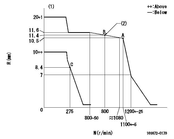
N:Pump speed
R:Rack position (mm)
(1)Target notch: K
(2)Set the torque control spring so that the injection quantity passes through point B.
----------
K=10
----------
----------
K=10
----------
Speed control lever angle
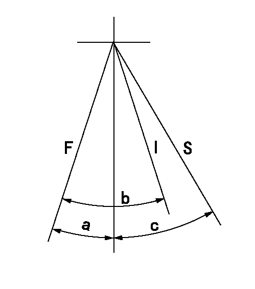
F:Full speed
I:Idle
S:Stop
----------
----------
a=10deg+-5deg b=24deg+-5deg c=32deg+-3deg
----------
----------
a=10deg+-5deg b=24deg+-5deg c=32deg+-3deg
Information:
ACTION REQUIRED
After Failure:
1 - Update Engine Software, refer to UENR0611 Troubleshooting ? ECM Software ? Install, ensure to follow the steps to save the Engine Configuration data. Refer to the table in Image 1 to determine the correct engine software file to apply.
2 - Service CCB Filter and replace with new filter, refer to SEBU8727 Operation and Maintenance Manual ? Engine Crankcase Breather element ? Replace.
3 - Remove Diesel Particulate Filter, Refer to UENR0621 Disassembly and Assembly - Diesel Particulate Filter - Remove - Wall Flow Diesel Particulate Filter.
4 - Move the Diesel Particulate Filter Assembly to a suitable work surface.
5 - Refer to UENR0619 Specifications - Diesel Particulate Filter (Wall Flow Diesel Particulate Filter(DPF)), remove V Band Clamps (1)&(4), carefully split assembly and remove DPF Canister element.
6 - Using new DPF Kit Filter, reassemble the Diesel Particulate Filter Assembly noting the alignment marks previously made in Step 3, refer to UENR0619 Specifications - Diesel Particulate Filter (Wall Flow Diesel Particulate Filter(DPF)).
7 - Reinstall the Diesel Particulate Filter assembly, Refer to UENR0621 Disassembly and Assembly - Diesel Particulate Filter - Install - Wall Flow Diesel Particulate Filter.
8 - As the DPF has been replaced, ensure the ?DPF Replacement Reset? procedure is performed using CAT ET, refer to UENR0611 Troubleshooting - Service Tool Features - Components Replacement Resets.
Image1
SERVICE CLAIM ALLOWANCES
Product smu/age whichever comes first Caterpillar Dealer Suggested Customer Suggested
Parts % Labor Hrs% Parts % Labor Hrs% Parts % Labor Hrs%
*******Group 1*******
0-3000 hrs,
0-60 mo 100.0% 100.0% 0.0% 0.0% 0.0% 0.0%
This is a 6.0-hour job for Group 1
Product smu/age whichever comes first Caterpillar Dealer Suggested Customer Suggested
Parts % Labor Hrs% Parts % Labor Hrs% Parts % Labor Hrs%
*******Group 2*******
0-3000 hrs,
0-60 mo 100.0% 100.0% 0.0% 0.0% 0.0% 0.0%
This is a 6.0-hour job for Group 2
PARTS DISPOSITION
Handle the parts in accordance with your Warranty Bulletin on warranty parts handling.
Have questions with 101672-0170?
Group cross 101672-0170 ZEXEL
Isuzu
101672-0170
5156003806
INJECTION-PUMP ASSEMBLY
D500
D500