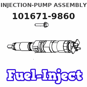
Information injection-pump assembly
ZEXEL
101671-9860
1016719860
NISSAN-DIESEL
1679095017
1679095017
Rating:
Service parts 101671-9860 INJECTION-PUMP ASSEMBLY:
1.
_
7.
COUPLING PLATE
8.
_
9.
_
11.
Nozzle and Holder
16600-95000
12.
Open Pre:MPa(Kqf/cm2)
17.7{180}

15.
NOZZLE SET
Include in #1:
101671-9860
as INJECTION-PUMP ASSEMBLY
Include in #2:
104740-8560
as _
Cross reference number
ZEXEL
101671-9860
1016719860
NISSAN-DIESEL
1679095017
1679095017
Zexel num
Bosch num
Firm num
Name
101671-9860
1679095017 NISSAN-DIESEL
INJECTION-PUMP ASSEMBLY
ND604 * K
ND604 * K
Calibration Data:
Adjustment conditions
Test oil
1404 Test oil ISO4113 or {SAEJ967d}
1404 Test oil ISO4113 or {SAEJ967d}
Test oil temperature
degC
40
40
45
Nozzle and nozzle holder
105780-8140
Bosch type code
EF8511/9A
Nozzle
105780-0000
Bosch type code
DN12SD12T
Nozzle holder
105780-2080
Bosch type code
EF8511/9
Opening pressure
MPa
17.2
Opening pressure
kgf/cm2
175
Injection pipe
Outer diameter - inner diameter - length (mm) mm 6-2-600
Outer diameter - inner diameter - length (mm) mm 6-2-600
Tester oil delivery pressure
kPa
157
157
157
Tester oil delivery pressure
kgf/cm2
1.6
1.6
1.6
Direction of rotation (viewed from drive side)
Right R
Right R
Injection timing adjustment
Direction of rotation (viewed from drive side)
Right R
Right R
Injection order
1-4-2-6-
3-5
Pre-stroke
mm
2.5
2.45
2.55
Beginning of injection position
Drive side NO.1
Drive side NO.1
Difference between angles 1
Cal 1-4 deg. 60 59.5 60.5
Cal 1-4 deg. 60 59.5 60.5
Difference between angles 2
Cyl.1-2 deg. 120 119.5 120.5
Cyl.1-2 deg. 120 119.5 120.5
Difference between angles 3
Cal 1-6 deg. 180 179.5 180.5
Cal 1-6 deg. 180 179.5 180.5
Difference between angles 4
Cal 1-3 deg. 240 239.5 240.5
Cal 1-3 deg. 240 239.5 240.5
Difference between angles 5
Cal 1-5 deg. 300 299.5 300.5
Cal 1-5 deg. 300 299.5 300.5
Injection quantity adjustment
Adjusting point
A
Rack position
12.3
Pump speed
r/min
750
750
750
Average injection quantity
mm3/st.
62.6
61.6
63.6
Max. variation between cylinders
%
0
-2
2
Basic
*
Fixing the lever
*
Injection quantity adjustment_02
Adjusting point
B
Rack position
12.2
Pump speed
r/min
1250
1250
1250
Average injection quantity
mm3/st.
66
63.5
68.5
Max. variation between cylinders
%
0
-4
4
Fixing the rack
*
Injection quantity adjustment_03
Adjusting point
-
Rack position
8.1+-0.5
Pump speed
r/min
225
225
225
Average injection quantity
mm3/st.
9
6.5
11.5
Max. variation between cylinders
%
0
-13
13
Fixing the rack
*
Remarks
Adjust only variation between cylinders; adjust governor according to governor specifications.
Adjust only variation between cylinders; adjust governor according to governor specifications.
Timer adjustment
Pump speed
r/min
300
Advance angle
deg.
0.5
Timer adjustment_02
Pump speed
r/min
600
Advance angle
deg.
1.3
0.8
1.8
Timer adjustment_03
Pump speed
r/min
1000
Advance angle
deg.
3.5
3
4
Timer adjustment_04
Pump speed
r/min
1250
Advance angle
deg.
5
4.5
5.5
Timer adjustment_05
Pump speed
r/min
-
Advance angle
deg.
6
6
6
Remarks
Measure the actual speed, stop
Measure the actual speed, stop
Test data Ex:
Governor adjustment
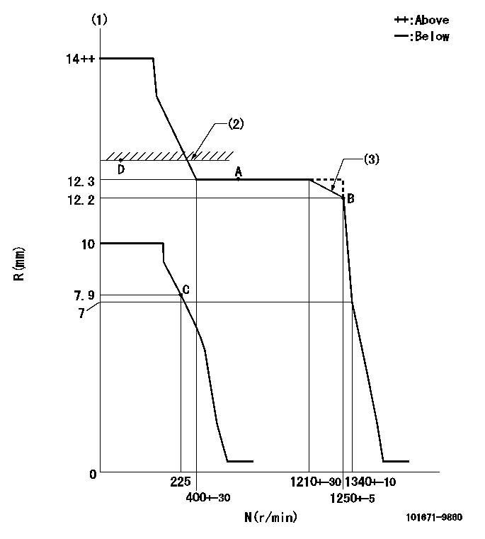
N:Pump speed
R:Rack position (mm)
(1)Target notch: K
(2)RACK LIMIT: RAL
(3)Set the torque spring.
----------
K=15 RAL=12.7+-0.1mm
----------
----------
K=15 RAL=12.7+-0.1mm
----------
Speed control lever angle

F:Full speed
I:Idle
S:Stop
----------
----------
a=23.5deg+-5deg b=32deg+-3deg c=33deg+-5deg
----------
----------
a=23.5deg+-5deg b=32deg+-3deg c=33deg+-5deg
Stop lever angle

N:Pump normal
S:Stop the pump.
----------
----------
a=26.5deg+-5deg b=53deg+-5deg
----------
----------
a=26.5deg+-5deg b=53deg+-5deg
Timing setting

(1)Pump vertical direction
(2)Coupling's key groove position at No 1 cylinder's beginning of injection
(3)-
(4)-
----------
----------
a=(30deg)
----------
----------
a=(30deg)
Information:
PROBLEM
The existing diesel exhaust fluid manifold can fail on certain 2570D, 2670D, 563D, and 573D Wheel Feller Bunchers, and 525D, 535D, 545D, and 555D Wheel Skidders. If the existing DEF manifold fails it can lead to inducements and eventual engine shutdown.
AFFECTED PRODUCT
Model Identification Number
2570D D2500112-00114
2670D D2600208-00211
525D GKP00477-00524, 527
535D MTP00386-00448, 450-453
545D KGP00254-00284, 287
555D PGY00153-00159
563D D6300115-00146
573D D7300209-00226
PARTS NEEDED
Qty
Part Number Description
1 3915262 GASKET
1 5280527 MANIFOLD GP
1 DCUSOFTWARE DCU SOFTWARE
1 ENGSOFTWARE ENGINE SOFTWARE
In order to allow equitable parts availability to all participating dealers, please limit your initial parts order to not exceed 29% of dealership population. This is an initial order recommendation only, and the ultimate responsibility for ordering the total number of parts needed to satisfy the program lies with the dealer.
ACTION REQUIRED
Update the Engine and DCU software files to the latest available in SIS Web. Replace the existing diesel exhaust fluid manifold with the 528-0527 diesel exhaust fluid manifold. Use a new 391-5262 gasket when installing a new manifold.
SERVICE CLAIM ALLOWANCES
Product smu/age whichever comes first Caterpillar Dealer Suggested Customer Suggested
Parts % Labor Hrs% Parts % Labor Hrs% Parts % Labor Hrs%
0-6000 hrs,
0-36 mo 100.0% 100.0% 0.0% 0.0% 0.0% 0.0%
6001-8000 hrs,
37-48 mo 33.0% 50.0% 0.0% 0.0% 50.0% 50.0%
This is a 2.0-hour job
PARTS DISPOSITION
Handle the parts in accordance with your Warranty Bulletin on warranty parts handling.
Have questions with 101671-9860?
Group cross 101671-9860 ZEXEL
Nissan-Diesel
101671-9860
1679095017
INJECTION-PUMP ASSEMBLY
ND604
ND604