Information injection-pump assembly
BOSCH
9 400 615 951
9400615951
ZEXEL
101671-9740
1016719740
NISSAN-DIESEL
1671395012
1671395012
Rating:
Service parts 101671-9740 INJECTION-PUMP ASSEMBLY:
1.
_
7.
COUPLING PLATE
8.
_
9.
_
11.
Nozzle and Holder
16600-95000
12.
Open Pre:MPa(Kqf/cm2)
17.7{180}

15.
NOZZLE SET
Include in #1:
101671-9740
as INJECTION-PUMP ASSEMBLY
Include in #2:
104740-8500
as _
Cross reference number
BOSCH
9 400 615 951
9400615951
ZEXEL
101671-9740
1016719740
NISSAN-DIESEL
1671395012
1671395012
Zexel num
Bosch num
Firm num
Name
101671-9740
9 400 615 951
1671395012 NISSAN-DIESEL
INJECTION-PUMP ASSEMBLY
ND604 * K 14BE PE6A PE
ND604 * K 14BE PE6A PE
Calibration Data:
Adjustment conditions
Test oil
1404 Test oil ISO4113 or {SAEJ967d}
1404 Test oil ISO4113 or {SAEJ967d}
Test oil temperature
degC
40
40
45
Nozzle and nozzle holder
105780-8140
Bosch type code
EF8511/9A
Nozzle
105780-0000
Bosch type code
DN12SD12T
Nozzle holder
105780-2080
Bosch type code
EF8511/9
Opening pressure
MPa
17.2
Opening pressure
kgf/cm2
175
Injection pipe
Outer diameter - inner diameter - length (mm) mm 6-2-600
Outer diameter - inner diameter - length (mm) mm 6-2-600
Tester oil delivery pressure
kPa
157
157
157
Tester oil delivery pressure
kgf/cm2
1.6
1.6
1.6
Direction of rotation (viewed from drive side)
Right R
Right R
Injection timing adjustment
Direction of rotation (viewed from drive side)
Right R
Right R
Injection order
1-4-2-6-
3-5
Pre-stroke
mm
2.5
2.45
2.55
Beginning of injection position
Drive side NO.1
Drive side NO.1
Difference between angles 1
Cal 1-4 deg. 60 59.5 60.5
Cal 1-4 deg. 60 59.5 60.5
Difference between angles 2
Cyl.1-2 deg. 120 119.5 120.5
Cyl.1-2 deg. 120 119.5 120.5
Difference between angles 3
Cal 1-6 deg. 180 179.5 180.5
Cal 1-6 deg. 180 179.5 180.5
Difference between angles 4
Cal 1-3 deg. 240 239.5 240.5
Cal 1-3 deg. 240 239.5 240.5
Difference between angles 5
Cal 1-5 deg. 300 299.5 300.5
Cal 1-5 deg. 300 299.5 300.5
Injection quantity adjustment
Adjusting point
A
Rack position
12.7
Pump speed
r/min
750
750
750
Average injection quantity
mm3/st.
69.2
67.7
70.7
Max. variation between cylinders
%
0
-2
2
Basic
*
Fixing the lever
*
Injection quantity adjustment_02
Adjusting point
B
Rack position
12.7
Pump speed
r/min
1350
1350
1350
Average injection quantity
mm3/st.
76.5
74.5
78.5
Max. variation between cylinders
%
0
-3
3
Fixing the lever
*
Injection quantity adjustment_03
Adjusting point
C
Rack position
8+-0.5
Pump speed
r/min
225
225
225
Average injection quantity
mm3/st.
9
7.8
10.2
Max. variation between cylinders
%
0
-13
13
Fixing the rack
*
Remarks
Adjust only variation between cylinders; adjust governor according to governor specifications.
Adjust only variation between cylinders; adjust governor according to governor specifications.
Timer adjustment
Pump speed
r/min
300
Advance angle
deg.
0.5
Timer adjustment_02
Pump speed
r/min
600
Advance angle
deg.
1.3
0.8
1.8
Timer adjustment_03
Pump speed
r/min
1000
Advance angle
deg.
3.5
3
4
Timer adjustment_04
Pump speed
r/min
1400
Advance angle
deg.
6
5.5
6.5
Remarks
Finish
Finish
Test data Ex:
Governor adjustment
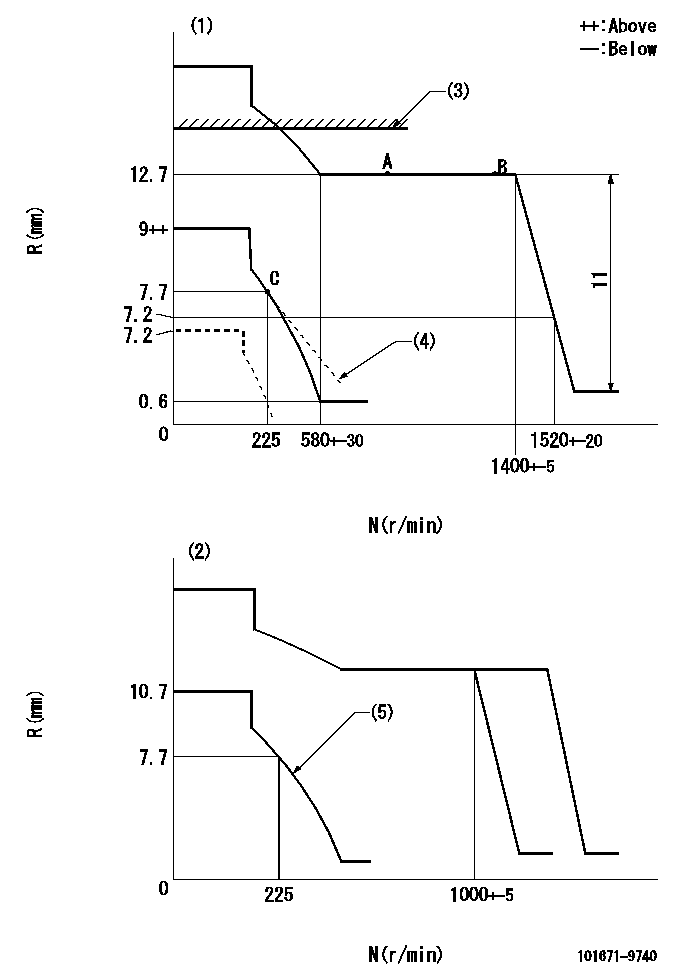
N:Pump speed
R:Rack position (mm)
(1)Adjust with speed control lever at full position (minimum-maximum speed specification)
(2)Adjust with the load control lever in the full position (variable speed specification).
(3)RACK LIMIT: RAL
(4)Damper spring setting: DL
(5)Set idle sub-spring
----------
RAL=13+-0.1mm DL=7.7-0.2mm
----------
----------
RAL=13+-0.1mm DL=7.7-0.2mm
----------
Speed control lever angle
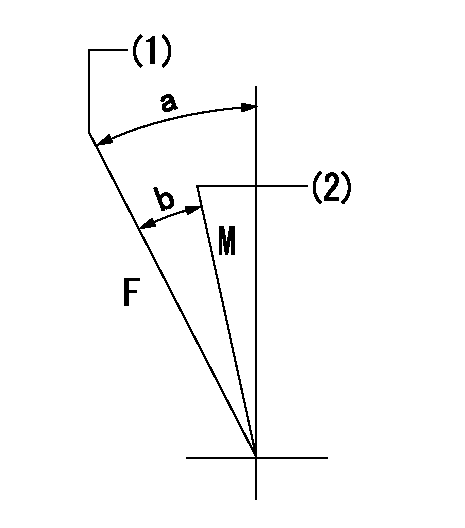
F:Full speed
M:Minimum-maximum speed
(1)Pump speed = aa
(2)Pump speed = bb
----------
aa=1400r/min bb=1000r/min
----------
a=20deg+-5deg b=11deg+-5deg
----------
aa=1400r/min bb=1000r/min
----------
a=20deg+-5deg b=11deg+-5deg
0000000901
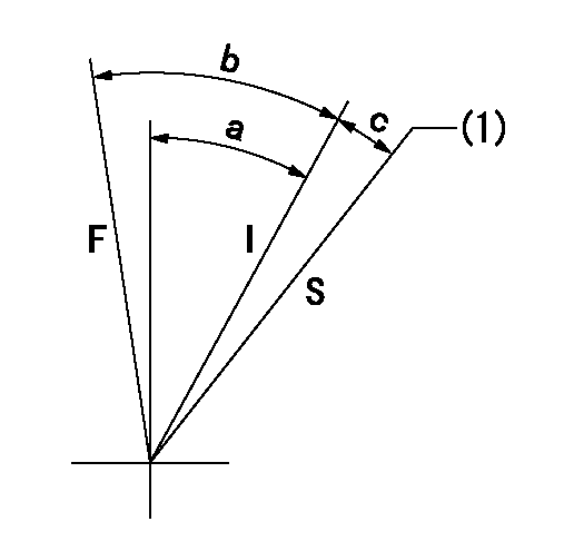
F:Full load
I:Idle
S:Stop
(1)Rack position aa (pump speed bb r/min )
----------
aa=7.2mm bb=0r/min
----------
a=26deg+-5deg b=36deg+-3deg c=12deg+-3deg
----------
aa=7.2mm bb=0r/min
----------
a=26deg+-5deg b=36deg+-3deg c=12deg+-3deg
Information:
ACTION REQUIRED
Refer to the attached Rework Procedure.
SERVICE CLAIM ALLOWANCES
Product smu/age whichever comes first Caterpillar Dealer Suggested Customer Suggested
Parts % Labor Hrs% Parts % Labor Hrs% Parts % Labor Hrs%
0-2000 hrs,
0-24 mo 100.0% 100.0% 0.0% 0.0% 0.0% 0.0%
This is a 2.0-hour job
PARTS DISPOSITION
Handle the parts in accordance with your Warranty Bulletin on warranty parts handling.
Rework Procedure
Use the procedures on the following pages in order to apply the updates to your machine.
- Park the machine on a firm, level surface.
- Fully retract and lower the boom.
- Place the travel select lever in the (N) NEUTRAL position.
- Apply Park Brake.
- Shut the engine off and remove the key from the MAIN switch located inside the engine compartment.
- Properly disconnect the battery.
- Place a Do Not Operate Tag on both the ignition key-switch and the steering wheel, stating that the machine should not be operated.
- Allow the engine area and antifreeze to cool down.
- Remove the cab rear cover.
- Use all applicable safety precautions while working on, around or under any machinery.
1. Locate DEF coolant supply hose (1) and DEF coolant return hose (2) on the engine. Refer to Image1.2.1.
Image1.2.1
2. Trace the routing of DEF coolant supply hose (1) on the engine to DEF coolant control valve (3) located in the middle of the frame. Refer to Image1.2.1 and 1.3.1.
Image1.3.1
3. Trace the routing of DEF coolant return hose (2) from the engine to DEF tank (4) located behind rear of the cab. Refer to Image1.2.1 and 1.4.1.
Image1.4.1
4. If the routing of DEF coolant supply hose (1) and DEF coolant return hose (2) are found to be correct, remount the cab rear cover and place the unit back in service.
5. If the routing of DEF coolant line (1) and DEF coolant return hose (2) are found to be incorrect, please continue the next steps to correct the DEF coolant line installation.
6. Remove all the cable straps that securing the two DEF coolant lines together or to other hoses. Refer to Image1.6.1. Some of the parts have been removed for clarity. Cut the 610cm of 5P-0767 Hose into two pieces: 330cm and 280cm.
Image1.6.1
7. Taking all precautions to minimize and contain any antifreeze spillage, disconnect DEF coolant supply hose (1) from DEF coolant control valve (3) and from the engine side DEF coolant supply port. The hose will not be reused. Retain the hose clamps for reuse. Refer to Image1.2.1 and 1.4.1.
8. Disconnect DEF coolant return hose (2) from DEF coolant tank (4) and from the engine side DEF coolant return port. The hose will not be reused. Retain the hose clamps for reuse. Refer to Image1.2.1 and 1.6.1.
9. Identify the new DEF coolant supply hose. It is the shorter
Have questions with 101671-9740?
Group cross 101671-9740 ZEXEL
Nissan-Diesel
101671-9740
9 400 615 951
1671395012
INJECTION-PUMP ASSEMBLY
ND604
ND604