Information injection-pump assembly
BOSCH
F 01G 09U 06E
f01g09u06e
ZEXEL
101641-9261
1016419261
NISSAN-DIESEL
16700L6000
16700l6000
Rating:
Cross reference number
BOSCH
F 01G 09U 06E
f01g09u06e
ZEXEL
101641-9261
1016419261
NISSAN-DIESEL
16700L6000
16700l6000
Zexel num
Bosch num
Firm num
Name
101641-9261
F 01G 09U 06E
16700L6000 NISSAN-DIESEL
INJECTION-PUMP ASSEMBLY
SD33T * K
SD33T * K
Calibration Data:
Adjustment conditions
Test oil
1404 Test oil ISO4113 or {SAEJ967d}
1404 Test oil ISO4113 or {SAEJ967d}
Test oil temperature
degC
40
40
45
Nozzle and nozzle holder
105780-8140
Bosch type code
EF8511/9A
Nozzle
105780-0000
Bosch type code
DN12SD12T
Nozzle holder
105780-2080
Bosch type code
EF8511/9
Opening pressure
MPa
17.2
Opening pressure
kgf/cm2
175
Injection pipe
Outer diameter - inner diameter - length (mm) mm 6-2-600
Outer diameter - inner diameter - length (mm) mm 6-2-600
Tester oil delivery pressure
kPa
157
157
157
Tester oil delivery pressure
kgf/cm2
1.6
1.6
1.6
Direction of rotation (viewed from drive side)
Right R
Right R
Injection timing adjustment
Direction of rotation (viewed from drive side)
Right R
Right R
Injection order
1-4-2-6-
3-5
Pre-stroke
mm
2.3
2.25
2.35
Beginning of injection position
Drive side NO.1
Drive side NO.1
Difference between angles 1
Cal 1-4 deg. 60 59.5 60.5
Cal 1-4 deg. 60 59.5 60.5
Difference between angles 2
Cyl.1-2 deg. 120 119.5 120.5
Cyl.1-2 deg. 120 119.5 120.5
Difference between angles 3
Cal 1-6 deg. 180 179.5 180.5
Cal 1-6 deg. 180 179.5 180.5
Difference between angles 4
Cal 1-3 deg. 240 239.5 240.5
Cal 1-3 deg. 240 239.5 240.5
Difference between angles 5
Cal 1-5 deg. 300 299.5 300.5
Cal 1-5 deg. 300 299.5 300.5
Injection quantity adjustment
Adjusting point
-
Rack position
13.5
Pump speed
r/min
800
800
800
Average injection quantity
mm3/st.
47.3
46.2
48.4
Max. variation between cylinders
%
0
-2.5
2.5
Basic
*
Fixing the rack
*
Standard for adjustment of the maximum variation between cylinders
*
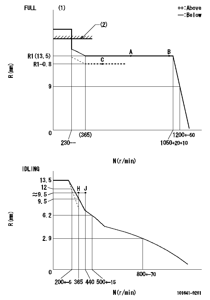
Injection quantity adjustment_02
Adjusting point
-
Rack position
9.9+-0.5
Pump speed
r/min
365
365
365
Average injection quantity
mm3/st.
9.2
8.1
10.3
Max. variation between cylinders
%
0
-15
15
Fixing the rack
*
Standard for adjustment of the maximum variation between cylinders
*
Remarks
Adjust only variation between cylinders; adjust governor according to governor specifications.
Adjust only variation between cylinders; adjust governor according to governor specifications.
Injection quantity adjustment_03
Adjusting point
A
Rack position
R1(13.5)
Pump speed
r/min
800
800
800
Average injection quantity
mm3/st.
47.3
46.3
48.3
Basic
*
Fixing the lever
*
Boost pressure
kPa
51.3
51.3
Boost pressure
mmHg
385
385
Injection quantity adjustment_04
Adjusting point
B
Rack position
R1(13.5)
Pump speed
r/min
1000
1000
1000
Average injection quantity
mm3/st.
48.7
44.7
52.7
Fixing the lever
*
Boost pressure
kPa
51.3
51.3
Boost pressure
mmHg
385
385
Injection quantity adjustment_05
Adjusting point
C
Rack position
R1-0.8
Pump speed
r/min
400
400
400
Average injection quantity
mm3/st.
36.2
32.2
40.2
Fixing the lever
*
Boost pressure
kPa
0
0
0
Boost pressure
mmHg
0
0
0
Boost compensator adjustment
Pump speed
r/min
400
400
400
Rack position
R1-0.8
Boost pressure
kPa
19.3
19.3
19.3
Boost pressure
mmHg
145
145
145
Boost compensator adjustment_02
Pump speed
r/min
400
400
400
Rack position
R1-0.5
Boost pressure
kPa
26
24.7
27.3
Boost pressure
mmHg
195
185
205
Boost compensator adjustment_03
Pump speed
r/min
400
400
400
Rack position
R1(13.5)
Boost pressure
kPa
38
38
38
Boost pressure
mmHg
285
285
285
Timer adjustment
Pump speed
r/min
550--
Advance angle
deg.
0
0
0
Remarks
Start
Start
Timer adjustment_02
Pump speed
r/min
500
Advance angle
deg.
0.5
Timer adjustment_03
Pump speed
r/min
700
Advance angle
deg.
1
Timer adjustment_04
Pump speed
r/min
1050
Advance angle
deg.
1.7
1.2
2.2
Timer adjustment_05
Pump speed
r/min
-
Advance angle
deg.
7.5
7.5
7.5
Remarks
Measure the actual speed, stop
Measure the actual speed, stop
Test data Ex:
Governor adjustment
N:Pump speed
R:Rack position (mm)
(1)Torque cam stamping: T1
(2)RACK LIMIT: RAL
----------
T1=89 RAL=13.8+0.2mm
----------
----------
T1=89 RAL=13.8+0.2mm
----------
Speed control lever angle
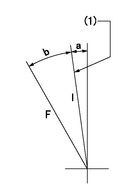
F:Full speed
I:Idle
(1)Stopper bolt set position 'H'
----------
----------
a=0deg+-5deg b=37deg+-3deg
----------
----------
a=0deg+-5deg b=37deg+-3deg
Stop lever angle
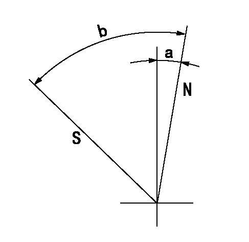
N:Pump normal
S:Stop the pump.
----------
----------
a=6deg+-5deg b=40deg+-5deg
----------
----------
a=6deg+-5deg b=40deg+-5deg
Timing setting

(1)Pump vertical direction
(2)Position of gear mark 'Y' at No 1 cylinder's beginning of injection
(3)B.T.D.C.: aa
(4)-
----------
aa=20deg
----------
a=(130deg)
----------
aa=20deg
----------
a=(130deg)
Information:
Model Views
The sample model view drawings show various typical Caterpillar 3408C and 3412C Engine features. The drawings are generic and do not reflect all available options. Because of individual applications, your engine may appear different from those illustrated.
3408 Model Views:(1) Exhaust(2) Oil Level Gauge (Dipstick)(3) Crankcase Breather(4) Oil Filler Cap(5) Manual Shutoff Shaft(6) Lifting Eye(7) Fuel Priming Pump(8) Fuel Pressure Gauge(9) Fuel Filter(10) Oil Filter(11) Supplemental Coolant Additive Element(12) Oil Drain(13) Air Inlet(14) Turbocharger(15) and Magnetic Pickup Location.
3412 Model Views:(1) Exhaust(2) Oil Level Gauge (Dipstick)(3) Crankcase Breather(4) Oil Filler Cap(5) Manual Shutoff Shaft(6) Lifting Eye(7) Fuel Priming Pump(8) Fuel Pressure Gauge(9) Fuel Filter(10) Oil Filter(11) Supplemental Coolant Additive Element(12) Oil Drain(13) Air Inlet(14) Turbocharger
Typical Generator Set (3408 Shown):(1) Control and Power Panel(2) Exhaust(3) Crankcase Breather(4) Oil Filler Cap(5) Governor Control Lever(6) Manual Shutoff Shaft(7) Radiator Cap(8) Lifting Location(9) Generator(10) Fuel Priming Pump(11) Fuel Filter(12) Oil Level Gauge (Dipstick)(13) Oil Filter(14) and Radiator DrainEngine Information
Engine Descriptions
The Caterpillar 3408C and 3412C Industrial Engines are available as precombustion chamber engines or as direct injection engines.A mechanical governor controls the fuel injection pump output, maintaining the engine rpm selected by the operator. Individual injection pumps (one for each cylinder) meter and pump fuel under high pressure to injection nozzles. Automatic timing advance provides the best fuel injection timing over the full range of engine speed.The fuel ratio control is located on the governor. The fuel ratio control restricts the fuel rack movement. Only the proper amount of fuel is allowed to be injected into the cylinders during acceleration. This minimizes exhaust smoke.Inlet air is filtered by an air cleaner. The air is compressed by a turbocharger before the air enters the engine cylinders. The turbocharger is driven by engine exhaust. The engines can be turbocharged, or turbocharged with jacket water aftercooling.The engines are four cycle engines. Each cylinder head has two inlet valves and two exhaust valves. The rocker arms and the valves are actuated by the camshaft. The action is performed by mechanical lifters and push rods.The cooling system consists of:* two thermostats (one for each bank) to regulate water temperature.* a gear driven centrifugal pump.* an oil cooler, and* a radiator (incorporating a shunt system).The engine lubricating oil, which is both cooled and filtered, is supplied by a gear-type pump. Bypass valves provide unrestricted flow of lubrication oil to the engine parts if oil viscosity is high, or if the oil cooler or the oil filter elements become plugged.Engine efficiency, efficiency of emission controls, and engine performance depend on adherence to proper operation and maintenance recommendations. Engine performance and efficiency also depend on the use of recommended coolant/antifreeze, fuels, and lubrication oils. Follow the recommended Maintenance Schedule found in this publication, paying attention to emission related components, air cleaner, oil, oil filter, fuel and fuel filter maintenance.EPG Information
Caterpillar Electrical Power Generation (EPG) Diesel Engines may be equipped with the Electronic Modular Control Panel II (EMCPII) and the SR4B Generator.The EMCPII provides accurate and reliable engine and generator control and monitoring.
Have questions with 101641-9261?
Group cross 101641-9261 ZEXEL
Nissan-Diesel
101641-9261
F 01G 09U 06E
16700L6000
INJECTION-PUMP ASSEMBLY
SD33T
SD33T