Information injection-pump assembly
BOSCH
9 400 610 026
9400610026
ZEXEL
101641-9210
1016419210

Rating:
Include in #2:
104749-3140
as _
Cross reference number
BOSCH
9 400 610 026
9400610026
ZEXEL
101641-9210
1016419210
Zexel num
Bosch num
Firm num
Name
Calibration Data:
Adjustment conditions
Test oil
1404 Test oil ISO4113 or {SAEJ967d}
1404 Test oil ISO4113 or {SAEJ967d}
Test oil temperature
degC
40
40
45
Nozzle and nozzle holder
105780-8140
Bosch type code
EF8511/9A
Nozzle
105780-0000
Bosch type code
DN12SD12T
Nozzle holder
105780-2080
Bosch type code
EF8511/9
Opening pressure
MPa
17.2
Opening pressure
kgf/cm2
175
Injection pipe
Outer diameter - inner diameter - length (mm) mm 6-2-600
Outer diameter - inner diameter - length (mm) mm 6-2-600
Tester oil delivery pressure
kPa
157
157
157
Tester oil delivery pressure
kgf/cm2
1.6
1.6
1.6
Direction of rotation (viewed from drive side)
Right R
Right R
Injection timing adjustment
Direction of rotation (viewed from drive side)
Right R
Right R
Injection order
1-4-2-6-
3-5
Pre-stroke
mm
2.3
2.25
2.35
Rack position
Point A R=A
Point A R=A
Beginning of injection position
Drive side NO.1
Drive side NO.1
Difference between angles 1
Cal 1-4 deg. 60 59.5 60.5
Cal 1-4 deg. 60 59.5 60.5
Difference between angles 2
Cyl.1-2 deg. 120 119.5 120.5
Cyl.1-2 deg. 120 119.5 120.5
Difference between angles 3
Cal 1-6 deg. 180 179.5 180.5
Cal 1-6 deg. 180 179.5 180.5
Difference between angles 4
Cal 1-3 deg. 240 239.5 240.5
Cal 1-3 deg. 240 239.5 240.5
Difference between angles 5
Cal 1-5 deg. 300 299.5 300.5
Cal 1-5 deg. 300 299.5 300.5
Injection quantity adjustment
Adjusting point
-
Rack position
13.7
Pump speed
r/min
1000
1000
1000
Average injection quantity
mm3/st.
48.3
47.2
49.4
Max. variation between cylinders
%
0
-2
2
Basic
*
Fixing the rack
*
Standard for adjustment of the maximum variation between cylinders
*
Injection quantity adjustment_02
Adjusting point
-
Rack position
9.9+-0.5
Pump speed
r/min
360
360
360
Average injection quantity
mm3/st.
7.5
6.4
8.6
Max. variation between cylinders
%
0
-15
15
Fixing the rack
*
Standard for adjustment of the maximum variation between cylinders
*
Remarks
Adjust only variation between cylinders; adjust governor according to governor specifications.
Adjust only variation between cylinders; adjust governor according to governor specifications.
Injection quantity adjustment_03
Adjusting point
A
Rack position
R1(13.7)
Pump speed
r/min
1000
1000
1000
Average injection quantity
mm3/st.
48.3
47.2
49.4
Basic
*
Fixing the lever
*
Boost pressure
kPa
53.3
53.3
Boost pressure
mmHg
400
400
Injection quantity adjustment_04
Adjusting point
B
Rack position
R1-0.7
Pump speed
r/min
2000
2000
2000
Average injection quantity
mm3/st.
47.2
45.2
49.2
Fixing the lever
*
Boost pressure
kPa
53.3
53.3
Boost pressure
mmHg
400
400
Injection quantity adjustment_05
Adjusting point
C
Rack position
R2(12.7)
Pump speed
r/min
500
500
500
Average injection quantity
mm3/st.
34.6
32.6
36.6
Fixing the lever
*
Boost pressure
kPa
0
0
0
Boost pressure
mmHg
0
0
0
Boost compensator adjustment
Pump speed
r/min
700
700
700
Rack position
R2(12.7)
Boost pressure
kPa
15.3
12.6
18
Boost pressure
mmHg
115
95
135
Boost compensator adjustment_02
Pump speed
r/min
700
700
700
Rack position
R1(13.7)
Boost pressure
kPa
46.7
40
46.7
Boost pressure
mmHg
350
300
350
Timer adjustment
Pump speed
r/min
550--
Advance angle
deg.
0
0
0
Remarks
Start
Start
Timer adjustment_02
Pump speed
r/min
500
Advance angle
deg.
0.5
Timer adjustment_03
Pump speed
r/min
1200
Advance angle
deg.
2.2
1.7
2.7
Timer adjustment_04
Pump speed
r/min
1900
Advance angle
deg.
6
5.5
6.5
Remarks
Finish
Finish
Test data Ex:
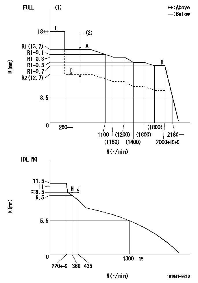
Governor adjustment

N:Pump speed
R:Rack position (mm)
(1)Torque cam stamping: T1
(2)Boost compensator stroke: BCL
----------
T1=74 BCL=1+-0.1mm
----------
----------
T1=74 BCL=1+-0.1mm
----------
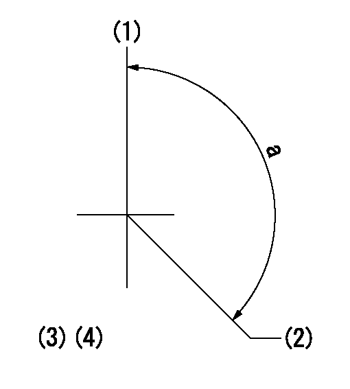
Speed control lever angle

F:Full speed
I:Idle
(1)Stopper bolt set position 'H'
----------
----------
a=37deg+-5deg b=43deg+-3deg
----------
----------
a=37deg+-5deg b=43deg+-3deg
Stop lever angle

N:Pump normal
S:Stop the pump.
----------
----------
a=10deg+-5deg b=40deg+-5deg
----------
----------
a=10deg+-5deg b=40deg+-5deg
Timing setting

(1)Pump vertical direction
(2)Position of gear mark 'Y' at No 1 cylinder's beginning of injection
(3)B.T.D.C.: aa
(4)-
----------
aa=20deg
----------
a=(130deg)
----------
aa=20deg
----------
a=(130deg)
Information:
Reassembly and adjustment (2-spring nozzle)
Adjust while assembling the parts by the following procedures.As the prelift is adjusted in 1/100 mm increments, use clean detergent to thoroughly remove dust and dirt before adjustment.The following special tools are necessary for adjustment. Adjusting Steps
(1) Adjustment of nozzle opening pressure(2) Selection of prelift adjusting shims(3) Adjustment of 2-spring adjusting pressure(4) * Check of needle valve full lift(5) Installation of prelift shims(6) * Checking of prelift(7) * Checking of 2-spring adjusting pressure(8) InspectionInspection make operations marked with * as necessary for inspection or confirmation.(1) Adjustment of nozzle valve opening pressure (a) Using the special tool, Retasining Nut for Adjustment, install the nozzle and needle valve to the nozzle holder. 1. Make sure that the knock pin has seated completely in the nozzle before tightening the retaining nut for adjustment. Tighten the retaining nut finger tight and then tighten to specified torque using a torque wrench.2. Remove the bolt from the tip of the retaining nut. (b) Insert 1st push rod 1st spring, valve opening pressure adjusting shim (first use about 1 mm thick one) and spacer to the nozzle holder. Then tighten the setscrew to specified torque. (c) Install the nozzle holder to the special tool, Nozzle Tester and adjust the shim thickness for nominal injection pressureShim types 0.50, 0.52, 0.54, 0.56, 0.58 0.60, 0.70, 0.80, 0.90, 1.00, 0.10, 0.20, 0.30, 0.40 mm 1. When using a shim, be sure to check its thickness by a micrometer.2. Use same shim for prelift adjustment.3. Use of a 0.02 mm thick shim changes the valve opening pressure by about 235 kPa (2.4 kgf/cm2)(2) Selection of prelift adjusting shim(a) 0 point adjustment of Adjusting Device Install the special tool, Dial Gauge to the special tool, Adjusting Device.Install the 2nd push rod to the special tool, Base and install the assembly to a vice.Set the pin and Adjusting Device as indicated in the above illustration and adjust 0 point of the Dial Gauge Use a 60.5 mm long pin.(b) Install the 2nd push rod to the nozzle holder. Do not install the 2nd spring and prelift adjusting shim. (c) Install the Adjusting Device to the setscrew using its intermediate screw.After installation, holding the Dial Gauge at its holder, move it up and down to check that the gauge operates smoothly.Push down the gauge, holding its holder and read its lift h. Read to 1/100 mm(d) Selection of prelift adjusting shim (e) Remove the Adjusting Device from the Nozzle Holder.(3) Adjustment of 2-spring adjusting pressure Install the 2nd spring, adjusting screw and lock nut to the nozzle holder. Do not install the prelift adjusting shim. Using the special tool, Nozzle Tester, adjust the adjusting screw for nominal injection pressure.After adjustment, tighten the lock nut to specified torque.(4) Checking full lift of needle valve (a) Install the special tools indicated in above illustration and set 0 point of the Dial Gauge.(b) Install the nozzle to the Nozzle Tester and operate the tester lever to bleed the inside of