Information injection-pump assembly
ZEXEL
101631-9760
1016319760

Rating:
Service parts 101631-9760 INJECTION-PUMP ASSEMBLY:
1.
_
6.
COUPLING PLATE
7.
COUPLING PLATE
8.
_
9.
_
11.
Nozzle and Holder
16600-20053
12.
Open Pre:MPa(Kqf/cm2)
9.8{100}

15.
NOZZLE SET
Include in #1:
101631-9760
as INJECTION-PUMP ASSEMBLY
Include in #2:
104740-3270
as _
Cross reference number
ZEXEL
101631-9760
1016319760
Zexel num
Bosch num
Firm num
Name
Calibration Data:
Adjustment conditions
Test oil
1404 Test oil ISO4113 or {SAEJ967d}
1404 Test oil ISO4113 or {SAEJ967d}
Test oil temperature
degC
40
40
45
Nozzle and nozzle holder
105780-8140
Bosch type code
EF8511/9A
Nozzle
105780-0000
Bosch type code
DN12SD12T
Nozzle holder
105780-2080
Bosch type code
EF8511/9
Opening pressure
MPa
17.2
Opening pressure
kgf/cm2
175
Injection pipe
Outer diameter - inner diameter - length (mm) mm 6-2-600
Outer diameter - inner diameter - length (mm) mm 6-2-600
Tester oil delivery pressure
kPa
157
157
157
Tester oil delivery pressure
kgf/cm2
1.6
1.6
1.6
Direction of rotation (viewed from drive side)
Right R
Right R
Injection timing adjustment
Direction of rotation (viewed from drive side)
Right R
Right R
Injection order
1-4-2-6-
3-5
Pre-stroke
mm
2.15
2.1
2.2
Rack position
R=11.7
Beginning of injection position
Drive side NO.1
Drive side NO.1
Difference between angles 1
Cal 1-4 deg. 60 59.5 60.5
Cal 1-4 deg. 60 59.5 60.5
Difference between angles 2
Cyl.1-2 deg. 120 119.5 120.5
Cyl.1-2 deg. 120 119.5 120.5
Difference between angles 3
Cal 1-6 deg. 180 179.5 180.5
Cal 1-6 deg. 180 179.5 180.5
Difference between angles 4
Cal 1-3 deg. 240 239.5 240.5
Cal 1-3 deg. 240 239.5 240.5
Difference between angles 5
Cal 1-5 deg. 300 299.5 300.5
Cal 1-5 deg. 300 299.5 300.5
Injection quantity adjustment
Adjusting point
-
Rack position
12.2
Pump speed
r/min
800
800
800
Average injection quantity
mm3/st.
32.1
31.1
33.1
Max. variation between cylinders
%
0
-2.5
2.5
Basic
*
Fixing the rack
*
Injection quantity adjustment_02
Adjusting point
-
Rack position
11.7
Pump speed
r/min
1900
1900
1900
Average injection quantity
mm3/st.
36.1
34.5
37.7
Max. variation between cylinders
%
0
-4
4
Fixing the rack
*
Injection quantity adjustment_03
Adjusting point
-
Rack position
8.6+-0.5
Pump speed
r/min
300
300
300
Average injection quantity
mm3/st.
7.5
6.5
8.5
Max. variation between cylinders
%
0
-15
15
Fixing the rack
*
Injection quantity adjustment_04
Adjusting point
-
Rack position
-
Pump speed
r/min
800
800
800
Average injection quantity
mm3/st.
32.1
31.6
32.6
Remarks
Set full load.
Set full load.
Timer adjustment
Pump speed
r/min
550--
Advance angle
deg.
0
0
0
Remarks
Start
Start
Timer adjustment_02
Pump speed
r/min
500
Advance angle
deg.
0.5
Timer adjustment_03
Pump speed
r/min
1100
Advance angle
deg.
1.7
1.2
2.2
Timer adjustment_04
Pump speed
r/min
1900
Advance angle
deg.
6
5.5
6.5
Remarks
Finish
Finish
Test data Ex:
Governor adjustment
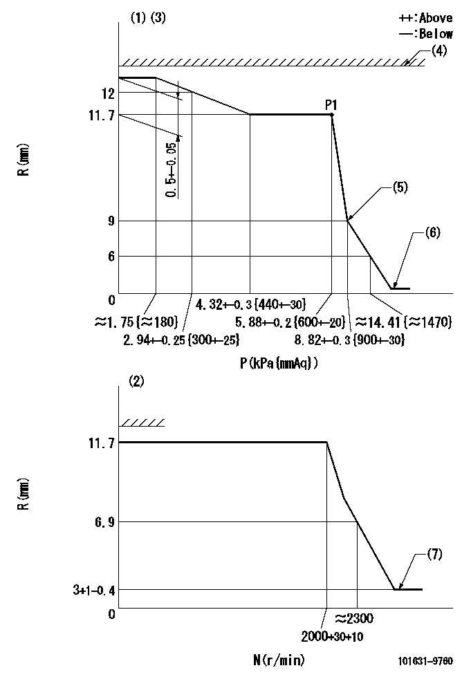
N:Pump speed
R:Rack position (mm)
P:Negative pressure
(1)Pneumatic governor
(2)Mechanical governor
(3)Acting negative pressure: P1
(4)RACK LIMIT: RAL
(5)Beginning of idle sub spring operation: L1
(6)With stopper disk.
(7)Injection quantity Q = Q1 or less
----------
RAL=17-0.3mm L1=9+0.3mm Q1=3mm3/st
----------
----------
RAL=17-0.3mm L1=9+0.3mm Q1=3mm3/st
----------
Speed control lever angle
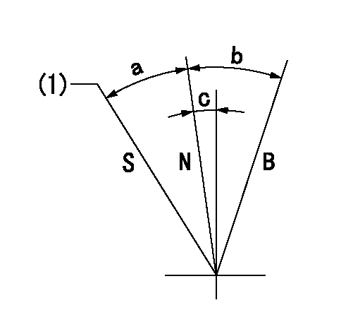
N:Normal
B:When boosted
S:Stop
(1)Rack position = aa
----------
aa=(1.8)mm
----------
a=20.5deg+-3deg b=8deg+-5deg c=0.5deg+-5deg
----------
aa=(1.8)mm
----------
a=20.5deg+-3deg b=8deg+-5deg c=0.5deg+-5deg
Timing setting

(1)Pump vertical direction
(2)Position of gear mark 'Y' at No 1 cylinder's beginning of injection
(3)B.T.D.C.: aa
(4)-
----------
aa=20deg
----------
a=(130deg)
----------
aa=20deg
----------
a=(130deg)
Information:
1. Drain the cooling system.2. Remove bolt (2) and spacer (1). 3. Remove clip (3) that holds line (4) to the cylinder head. 4. Remove bolts (5) that hold fuel filter base and filter (6) to the cylinder head. 5. Fasten a chain and hoist to the cylinder head lifting brackets. Remove the bolts and nuts that hold the cylinder head. Remove the cylinder head. Weight of the cylinder head is 41 kg (90 lb.). 6. Remove cylinder head gasket (7).7. Check the condition of the cylinder head assembly before installation.Install Cylinder Head Assembly
1. Use a tap of the correct size to clean each threaded hole in the cylinder block for the cylinder head mounting bolts.2. Thoroughly clean the surface for the cylinder head gasket on the cylinder head assembly and cylinder block.
Be sure the gasket is positioned so that all coolant passages in the cylinder block can be seen through the gasket.
3. Put cylinder head gasket (1) in place on the studs in the cylinder block. 4. Put the cylinder head in position on the studs.5. Put clean engine oil on the bolt threads, and install the bolts that hold the cylinder head. 6. Tighten the bolts and nuts in the number sequence shown as follows:a. Tighten all bolts and nuts in number sequence to a torque of 45 N m (35 lb.ft.).b. Tighten all bolts and nuts in number sequence to a torque of 95 N m (70 lb.ft.).c. Again, tighten all bolts and nuts in number sequence to a final torque of 135 N m (100 lb.ft.). Retighten the cylinder head bolts and nuts after the engine has run under part load for approximately thirty minutes.a. If the bolts and nuts move before the correct final torque is reached, retighten every thing in the sequence again to the final torque of 135 N m (100 lb.ft.).b. If the bolts and nuts do not move before the correct final torque is reached, back each one off 30 to 60°, and retighten again, in the sequence shown, to the final torque. After all the bolts and nuts are retightened, check the first 10 positions to make sure they are tightened to the correct torque. 7. Install fuel filter base and filter (2) on the cylinder head with bolts (3).8. Install clip (4) that holds fuel line (5) to the cylinder head.9. Install the alternator bracket bolt and spacer in the cylinder head.End By:a. install fuel injection nozzle assembliesb. install fuel injection linesc. install inlet and exhaust manifoldd. install rocker shaft and push rods