Information injection-pump assembly
BOSCH
9 400 610 278
9400610278
ZEXEL
101631-9753
1016319753
NISSAN-DIESEL
16700C8603
16700c8603

Rating:
Service parts 101631-9753 INJECTION-PUMP ASSEMBLY:
1.
_
6.
COUPLING PLATE
7.
COUPLING PLATE
8.
_
9.
_
11.
Nozzle and Holder
16600-36W00
12.
Open Pre:MPa(Kqf/cm2)
9.8{100}

15.
NOZZLE SET
Include in #1:
101631-9753
as INJECTION-PUMP ASSEMBLY
Include in #2:
104740-3260
as _
Cross reference number
BOSCH
9 400 610 278
9400610278
ZEXEL
101631-9753
1016319753
NISSAN-DIESEL
16700C8603
16700c8603
Zexel num
Bosch num
Firm num
Name
101631-9753
9 400 610 278
16700C8603 NISSAN-DIESEL
INJECTION-PUMP ASSEMBLY
SD33 * K 14BE PE6A PE
SD33 * K 14BE PE6A PE
Calibration Data:
Adjustment conditions
Test oil
1404 Test oil ISO4113 or {SAEJ967d}
1404 Test oil ISO4113 or {SAEJ967d}
Test oil temperature
degC
40
40
45
Nozzle and nozzle holder
105780-8140
Bosch type code
EF8511/9A
Nozzle
105780-0000
Bosch type code
DN12SD12T
Nozzle holder
105780-2080
Bosch type code
EF8511/9
Opening pressure
MPa
17.2
Opening pressure
kgf/cm2
175
Injection pipe
Outer diameter - inner diameter - length (mm) mm 6-2-600
Outer diameter - inner diameter - length (mm) mm 6-2-600
Tester oil delivery pressure
kPa
157
157
157
Tester oil delivery pressure
kgf/cm2
1.6
1.6
1.6
Direction of rotation (viewed from drive side)
Right R
Right R
Injection timing adjustment
Direction of rotation (viewed from drive side)
Right R
Right R
Injection order
1-4-2-6-
3-5
Pre-stroke
mm
2.15
2.1
2.2
Rack position
R=11.6
Beginning of injection position
Drive side NO.1
Drive side NO.1
Difference between angles 1
Cal 1-4 deg. 60 59.5 60.5
Cal 1-4 deg. 60 59.5 60.5
Difference between angles 2
Cyl.1-2 deg. 120 119.5 120.5
Cyl.1-2 deg. 120 119.5 120.5
Difference between angles 3
Cal 1-6 deg. 180 179.5 180.5
Cal 1-6 deg. 180 179.5 180.5
Difference between angles 4
Cal 1-3 deg. 240 239.5 240.5
Cal 1-3 deg. 240 239.5 240.5
Difference between angles 5
Cal 1-5 deg. 300 299.5 300.5
Cal 1-5 deg. 300 299.5 300.5
Injection quantity adjustment
Adjusting point
-
Rack position
11.6
Pump speed
r/min
800
800
800
Average injection quantity
mm3/st.
33.1
32.1
34.1
Max. variation between cylinders
%
0
-2.5
2.5
Basic
*
Fixing the rack
*
Injection quantity adjustment_02
Adjusting point
-
Rack position
8.1+-0.5
Pump speed
r/min
300
300
300
Average injection quantity
mm3/st.
7.5
6.4
8.6
Max. variation between cylinders
%
0
-15
15
Fixing the rack
*
Timer adjustment
Pump speed
r/min
550--
Advance angle
deg.
0
0
0
Remarks
Start
Start
Timer adjustment_02
Pump speed
r/min
500
Advance angle
deg.
0.5
Timer adjustment_03
Pump speed
r/min
1100
Advance angle
deg.
2.2
1.7
2.7
Timer adjustment_04
Pump speed
r/min
1900
Advance angle
deg.
7.5
7
8
Remarks
Finish
Finish
Test data Ex:
Governor adjustment
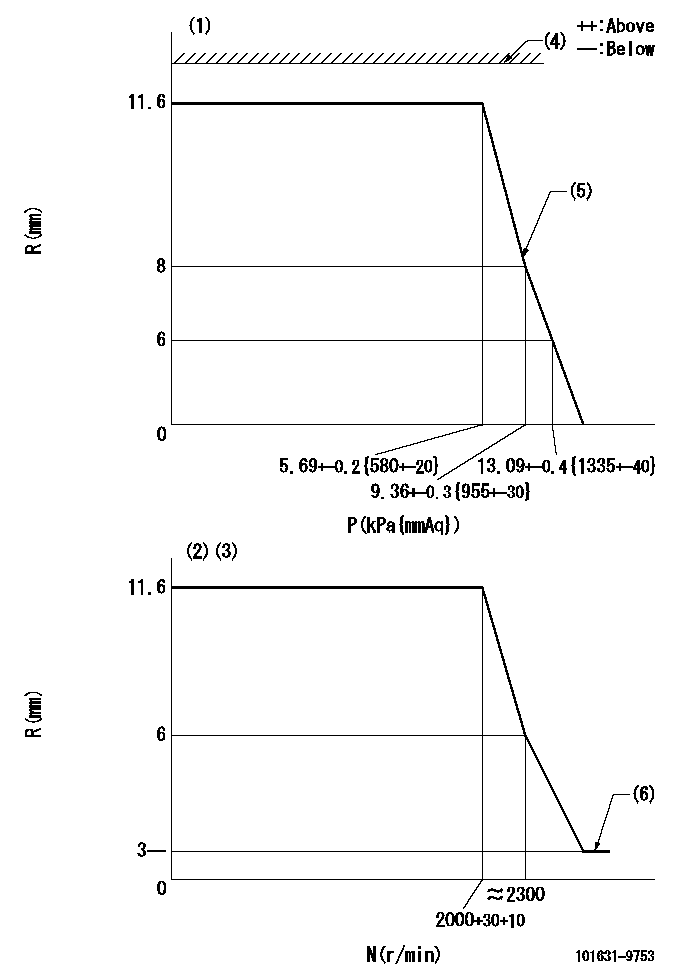
N:Pump speed
R:Rack position (mm)
P:Negative pressure
(1)Pneumatic governor
(2)Mechanical governor
(3)Acting negative pressure: P1
(4)RACK LIMIT: RAL
(5)Beginning of idle sub spring operation: L1
(6)Injection quantity Q = Q1 or less
----------
P1=3.63+-0.2kPa(370+-20mmAq) RAL=16-0.3mm L1=8+0.3mm Q1=3mm3/st
----------
----------
P1=3.63+-0.2kPa(370+-20mmAq) RAL=16-0.3mm L1=8+0.3mm Q1=3mm3/st
----------
0000001101
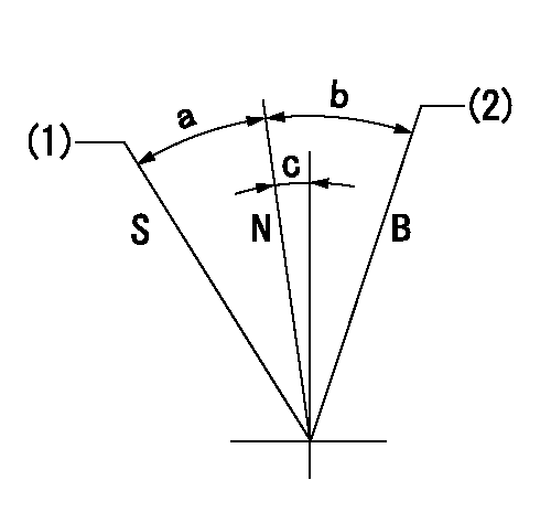
N:Normal
B:When boosted
S:Stop
(1)Rack position = aa
(2)Rack position bb
----------
aa=0mm bb=16mm
----------
a=23.5deg+-3deg b=8.5deg+-5deg c=2deg+-5deg
----------
aa=0mm bb=16mm
----------
a=23.5deg+-3deg b=8.5deg+-5deg c=2deg+-5deg
Timing setting

(1)Pump vertical direction
(2)Position of gear mark 'Y' at No 1 cylinder's beginning of injection
(3)B.T.D.C.: aa
(4)-
----------
aa=20deg
----------
a=(130deg)
----------
aa=20deg
----------
a=(130deg)
Information:
Start By:a. remove rocker shaft and push rods Valve guide seals for the inlet valves and O-ring seals for the exhaust valves can be removed without removal of the cylinder head by use of the method shown. Pressure air is used to hold the valves in position while the valve springs and retainers are removed. Use an old fuel injection nozzle to make an air chuck adapter. 1. Remove the fuel injection nozzle assembly, and put the piston on TDC (top dead center) for the respective cylinder for which the valve stem seal and O-ring seals are to be removed.2. Install air chuck adapter (2). Fasten a pressure air source to pressurize the cylinder.3. Use tooling (A) to compress the valve springs. Use magnet bar (1) to hold the keepers.4. Remove tool (A), and remove the valve springs and retainer. 5. Remove exhaust valve O-ring seal (3) and inlet valve guide seal (4).
Do not release air pressure in the cylinder until the valve springs and retainer have been installed. Failure to do so will let the valve fall into the top of the piston. If the piston is not at TDC (top dead center) the valve can fall into the cylinder making cylinder head removal necessary.
Install Valve Guide Seals
1. Install spring seating washer (1). 2. Put clean engine oil on the part of valve guide seal (2) that makes contact with the valve stem. Install valve guide seal (2).
The closed coil of the spring must be toward the cylinder rod.
3. Put inner and outer springs (4) and retainer (3) in position.
The locks can be thrown from the valve when the compressor is released if they are not in their correct position on the valve stem.
4. Use tool (A) to compress the valve springs so the keepers can be installed.5. Use tool (B) to install the keepers.6. Repeat Steps 1-4 for O-ring seals (5) on the exhaust valve.7. Move the piston off T.D.C. (top dead center) and tap the valve spring retainer with a soft hammer to be sure the retainers are properly seated.8. Install the fuel injection nozzle assembly.End By:a. install rocker shaft and push rods
Have questions with 101631-9753?
Group cross 101631-9753 ZEXEL
Nissan-Diesel
Nissan-Diesel
101631-9753
9 400 610 278
16700C8603
INJECTION-PUMP ASSEMBLY
SD33
SD33