Information injection-pump assembly
BOSCH
9 400 610 277
9400610277
ZEXEL
101631-9742
1016319742
NISSAN-DIESEL
16700C8602
16700c8602

Rating:
Service parts 101631-9742 INJECTION-PUMP ASSEMBLY:
1.
_
6.
COUPLING PLATE
7.
COUPLING PLATE
8.
_
9.
_
11.
Nozzle and Holder
16600-36W00
12.
Open Pre:MPa(Kqf/cm2)
9.8{100}

15.
NOZZLE SET
Include in #1:
101631-9742
as INJECTION-PUMP ASSEMBLY
Include in #2:
104740-3250
as _
Cross reference number
BOSCH
9 400 610 277
9400610277
ZEXEL
101631-9742
1016319742
NISSAN-DIESEL
16700C8602
16700c8602
Zexel num
Bosch num
Firm num
Name
101631-9742
9 400 610 277
16700C8602 NISSAN-DIESEL
INJECTION-PUMP ASSEMBLY
SD33 * K 14BE PE6A PE
SD33 * K 14BE PE6A PE
Calibration Data:
Adjustment conditions
Test oil
1404 Test oil ISO4113 or {SAEJ967d}
1404 Test oil ISO4113 or {SAEJ967d}
Test oil temperature
degC
40
40
45
Nozzle and nozzle holder
105780-8140
Bosch type code
EF8511/9A
Nozzle
105780-0000
Bosch type code
DN12SD12T
Nozzle holder
105780-2080
Bosch type code
EF8511/9
Opening pressure
MPa
17.2
Opening pressure
kgf/cm2
175
Injection pipe
Outer diameter - inner diameter - length (mm) mm 6-2-600
Outer diameter - inner diameter - length (mm) mm 6-2-600
Tester oil delivery pressure
kPa
157
157
157
Tester oil delivery pressure
kgf/cm2
1.6
1.6
1.6
Direction of rotation (viewed from drive side)
Right R
Right R
Injection timing adjustment
Direction of rotation (viewed from drive side)
Right R
Right R
Injection order
1-4-2-6-
3-5
Pre-stroke
mm
2.15
2.1
2.2
Rack position
R=11.6
Beginning of injection position
Drive side NO.1
Drive side NO.1
Difference between angles 1
Cal 1-4 deg. 60 59.5 60.5
Cal 1-4 deg. 60 59.5 60.5
Difference between angles 2
Cyl.1-2 deg. 120 119.5 120.5
Cyl.1-2 deg. 120 119.5 120.5
Difference between angles 3
Cal 1-6 deg. 180 179.5 180.5
Cal 1-6 deg. 180 179.5 180.5
Difference between angles 4
Cal 1-3 deg. 240 239.5 240.5
Cal 1-3 deg. 240 239.5 240.5
Difference between angles 5
Cal 1-5 deg. 300 299.5 300.5
Cal 1-5 deg. 300 299.5 300.5
Injection quantity adjustment
Adjusting point
-
Rack position
11.6
Pump speed
r/min
800
800
800
Average injection quantity
mm3/st.
33.1
32.1
34.1
Max. variation between cylinders
%
0
-2.5
2.5
Basic
*
Fixing the rack
*
Injection quantity adjustment_02
Adjusting point
-
Rack position
8.1+-0.5
Pump speed
r/min
300
300
300
Average injection quantity
mm3/st.
7.5
6.4
8.6
Max. variation between cylinders
%
0
-15
15
Fixing the rack
*
Timer adjustment
Pump speed
r/min
550--
Advance angle
deg.
0
0
0
Remarks
Start
Start
Timer adjustment_02
Pump speed
r/min
500
Advance angle
deg.
0.5
Timer adjustment_03
Pump speed
r/min
1100
Advance angle
deg.
2.2
1.7
2.7
Timer adjustment_04
Pump speed
r/min
1900
Advance angle
deg.
7.5
7
8
Remarks
Finish
Finish
Test data Ex:
Governor adjustment
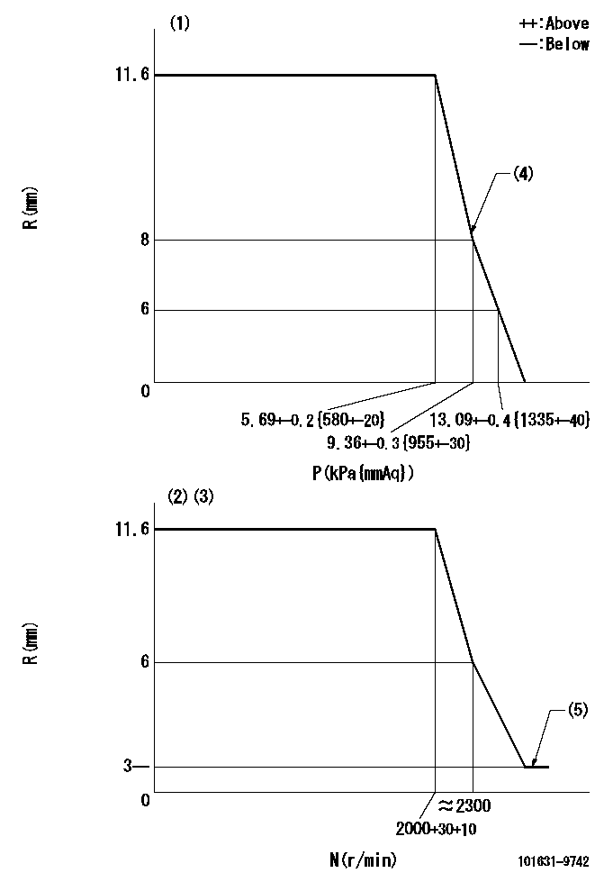
N:Pump speed
R:Rack position (mm)
P:Negative pressure
(1)Pneumatic governor
(2)Mechanical governor
(3)Acting negative pressure: P1
(4)Beginning of idle sub spring operation: L1
(5)Injection quantity Q = Q1 or less
----------
P1=3.63+-0.2kPa(370+-20mmAq) L1=8+0.3mm Q1=3mm3/st
----------
----------
P1=3.63+-0.2kPa(370+-20mmAq) L1=8+0.3mm Q1=3mm3/st
----------
0000001101
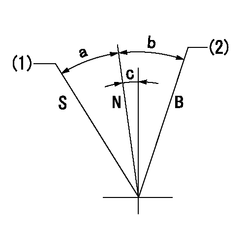
N:Normal
B:When boosted
S:Stop
(1)Rack position = aa
(2)Rack position bb
----------
aa=0mm bb=18mm
----------
a=23.5deg+-3deg b=12deg+-5deg c=2deg+-5deg
----------
aa=0mm bb=18mm
----------
a=23.5deg+-3deg b=12deg+-5deg c=2deg+-5deg
Timing setting

(1)Pump vertical direction
(2)Position of gear mark 'Y' at No 1 cylinder's beginning of injection
(3)B.T.D.C.: aa
(4)-
----------
aa=20deg
----------
a=(130deg)
----------
aa=20deg
----------
a=(130deg)
Information:
1. Remove the bolts that hold timing gear case cover (1) to the timing gear case. Remove the timing gear case cover.
Later type crankshaft front seals (with protruding dust lip) do not use a slinger. Seal damage can occur if a slinger is used.
2. On earlier models, remove slinger (2). 3. Remove seal (3) from timing gear case cover (1).Install Timing Gear Case Cover
*New, improved crankshaft front oil seals have a dust lip protrusion molded on to the front of the seal. The centering tool (PD162) must be reworked as shown in this illustration to prevent damage to this dust lip when the new type seal is installed. 1. Put timing gear case cover (1) in position with a new gasket. Install the bolts and lockwashers that hold it, but do not tighten them at this time. Use tool (A) to properly locate the timing gear case cover with respect to the crankshaft.2. Install tool (A) over the crankshaft and into the timing gear case cover seal bore. Hold tool (A) firmly in the timing gear case cover. Tighten the bolts that hold the timing gear case cover.
Washer (2) replaces the slinger, which is not used on later type seals with protruding dust lip.
3. Install washer (2). 4. Put seal (3) in position in the timing gear case cover. Install the seal with the lip toward the crankshaft gear. The seal surface must be clean and dry. Do not handle the lip of the seal.5. Use tool (A) and a soft hammer to install seal (3). Install the seal until it is 3.17 mm (.125 in) below the surface of the timing gear case cover.End By:a. install crankshaft pulleyb. install fan assembly
Have questions with 101631-9742?
Group cross 101631-9742 ZEXEL
Nissan-Diesel
Nissan-Diesel
101631-9742
9 400 610 277
16700C8602
INJECTION-PUMP ASSEMBLY
SD33
SD33