Information injection-pump assembly
ZEXEL
101631-9730
1016319730
NISSAN-DIESEL
1679090164
1679090164

Rating:
Service parts 101631-9730 INJECTION-PUMP ASSEMBLY:
1.
_
5.
AUTOM. ADVANCE MECHANIS
6.
COUPLING PLATE
7.
COUPLING PLATE
8.
_
9.
_
11.
Nozzle and Holder
12.
Open Pre:MPa(Kqf/cm2)
9.8(100)

15.
NOZZLE SET
Include in #1:
101631-9730
as INJECTION-PUMP ASSEMBLY
Include in #2:
104740-3240
as _
Cross reference number
ZEXEL
101631-9730
1016319730
NISSAN-DIESEL
1679090164
1679090164
Zexel num
Bosch num
Firm num
Name
101631-9730
1679090164 NISSAN-DIESEL
INJECTION-PUMP ASSEMBLY
SD33 * K
SD33 * K
Calibration Data:
Adjustment conditions
Test oil
1404 Test oil ISO4113 or {SAEJ967d}
1404 Test oil ISO4113 or {SAEJ967d}
Test oil temperature
degC
40
40
45
Nozzle and nozzle holder
105780-8140
Bosch type code
EF8511/9A
Nozzle
105780-0000
Bosch type code
DN12SD12T
Nozzle holder
105780-2080
Bosch type code
EF8511/9
Opening pressure
MPa
17.2
Opening pressure
kgf/cm2
175
Injection pipe
Outer diameter - inner diameter - length (mm) mm 6-2-600
Outer diameter - inner diameter - length (mm) mm 6-2-600
Tester oil delivery pressure
kPa
157
157
157
Tester oil delivery pressure
kgf/cm2
1.6
1.6
1.6
Direction of rotation (viewed from drive side)
Right R
Right R
Injection timing adjustment
Direction of rotation (viewed from drive side)
Right R
Right R
Injection order
1-4-2-6-
3-5
Pre-stroke
mm
2.3
2.25
2.35
Beginning of injection position
Drive side NO.1
Drive side NO.1
Difference between angles 1
Cal 1-4 deg. 60 59.5 60.5
Cal 1-4 deg. 60 59.5 60.5
Difference between angles 2
Cyl.1-2 deg. 120 119.5 120.5
Cyl.1-2 deg. 120 119.5 120.5
Difference between angles 3
Cal 1-6 deg. 180 179.5 180.5
Cal 1-6 deg. 180 179.5 180.5
Difference between angles 4
Cal 1-3 deg. 240 239.5 240.5
Cal 1-3 deg. 240 239.5 240.5
Difference between angles 5
Cal 1-5 deg. 300 299.5 300.5
Cal 1-5 deg. 300 299.5 300.5
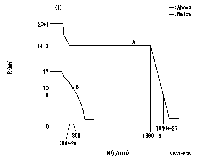
Injection quantity adjustment
Adjusting point
A
Rack position
14.3
Pump speed
r/min
1550
1550
1550
Average injection quantity
mm3/st.
37
36
38
Max. variation between cylinders
%
0
-2.5
2.5
Basic
*
Fixing the lever
*
Injection quantity adjustment_02
Adjusting point
B
Rack position
10.3+-0.
5
Pump speed
r/min
300
300
300
Average injection quantity
mm3/st.
75
74
76
Max. variation between cylinders
%
0
-15
15
Fixing the rack
*
Remarks
Adjust only variation between cylinders; adjust governor according to governor specifications.
Adjust only variation between cylinders; adjust governor according to governor specifications.
Timer adjustment
Pump speed
r/min
500+-50
Advance angle
deg.
0
0
0
Remarks
Start
Start
Timer adjustment_02
Pump speed
r/min
700
Advance angle
deg.
1
0.5
1.5
Timer adjustment_03
Pump speed
r/min
1100
Advance angle
deg.
2.8
2.1
3.6
Timer adjustment_04
Pump speed
r/min
1500
Advance angle
deg.
5
4.5
5.5
Timer adjustment_05
Pump speed
r/min
1800
Advance angle
deg.
7.5
7
8
Remarks
Finish
Finish
Test data Ex:
Governor adjustment
N:Pump speed
R:Rack position (mm)
(1)Target notch: K
----------
K=6
----------
----------
K=6
----------
Speed control lever angle
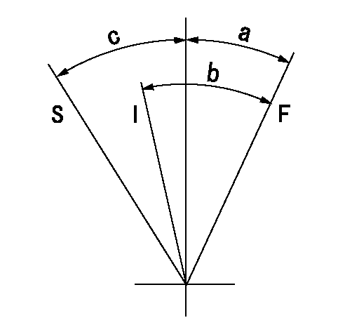
F:Full speed
I:Idle
S:Stop
----------
----------
a=22deg+-5deg b=36deg+-5deg c=32deg+-3deg
----------
----------
a=22deg+-5deg b=36deg+-5deg c=32deg+-3deg
Stop lever angle
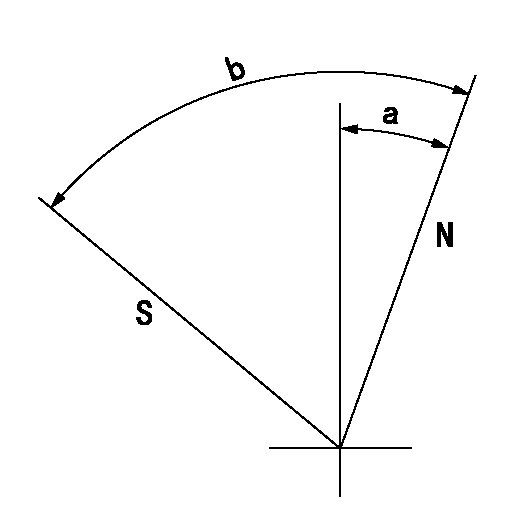
N:Pump normal
S:Stop the pump.
----------
----------
a=10deg+-5deg b=53deg+-5deg
----------
----------
a=10deg+-5deg b=53deg+-5deg
0000001501 GOV FULL LOAD ADJUSTMENT
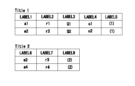
Title1:Full load stopper adjustment
Title2:Governor set speed
LABEL1:Distinguishing
LABEL2:Pump speed (r/min)
LABEL3:Ave. injection quantity (mm3/st)
LABEL4:Max. var. bet. cyl.
LABEL5:Remarks
LABEL6:Distinguishing
LABEL7:Governor set speed (r/min)
LABEL8:Remarks
(1)Adjustment conditions are the same as those for measuring injection quantity.
(2)-
----------
----------
a1=M a2=F r1=1550r/min r2=1550r/min Q1=37+-1mm3/st Q2=33.2+-1mm3/st c1=+-2.5% c2=+-2.5% a3= a4= r3= r4=
----------
----------
a1=M a2=F r1=1550r/min r2=1550r/min Q1=37+-1mm3/st Q2=33.2+-1mm3/st c1=+-2.5% c2=+-2.5% a3= a4= r3= r4=
Timing setting

(1)Pump vertical direction
(2)Position of gear mark 'Y' at No 1 cylinder's beginning of injection
(3)-
(4)-
----------
----------
a=(130deg)
----------
----------
a=(130deg)
Information:
1. Disconnect two Fuel lines (1).2. Remove four bolts (2) and remove fuel transfer pump and gasket. The following steps are for the installation of the fuel transfer pump.3. Position the gasket and fuel transfer pump then install bolts (2).4. Connect fuel lines (1).5. Prime the fuel system. See the MAINTENANCE MANUAL.Disassemble Fuel Transfer Pump
Start By:a. remove fuel transfer pump 1. Remove cover (1) from the fuel transfer pump. 2. Remove strainer (2). 3. Remove valve housing (3) from body (4). 4. Use a pencil grinder to remove the staked metal that holds inlet check valve (6) and outlet check valve (5) in place. Remove check valves (5) and (6). 5. Push the center of the diaphragm down and turn it 90° to disengage the actuator rod from the actuator arm. Remove diaphragm (7). 6. Remove spring (8). 7. Remove retainer (9). 8. Remove lever (12), shaft (11) and arm (10) as an assembly. 9. If necessary, remove washers (13) from shaft (11). Remove shaft (11) and separate arm (10) from lever (12). 10. If necessary, remove primer (14) and spring.11. Thoroughly inspect all parts of the fuel transfer pump. A repair kit is available to rebuild the fuel transfer pump. The following steps are for the assembly of the fuel transfer pump. 12. Install primer (14) and the spring on to body (4). 13. Install lever (12) into arm (10) and install pin (11) through the arm and lever. Put washer (13) on each side of arm (10). 14. Put spring (15) into position on the boss in body (4). Install arm (10) and lever (12) as an assembly into body (4). Be sure spring (15) engages with the tang on lever (12). 15. Install two retainers (9) to hold shaft (11) and arm and lever assembly in body (4). 16. Install spring (8) into body (4). 17. Install diaphragm (7) into body (4). Put the flat on the actuator rod in alignment with lever (12). Push the center of the diaphragm down and turn it 90° to engage the actuator rod with the actuator arm. 18. Install a gasket and check valve (6) and gasket and check valve (5) in valve body (3). Stake valve body (3) around each check valve to hold them in position. Make the stake marks at a different location than the original stake marks. 19. Put the valve body in place on diaphragm (7) and install the screws that hold it. 20. Put strainer (2) in position on valve body (3). 21. Install a new gasket in cover (1) and Install cover (1) on body.End By:a. install fuel transfer pump
Start By:a. remove fuel transfer pump 1. Remove cover (1) from the fuel transfer pump. 2. Remove strainer (2). 3. Remove valve housing (3) from body (4). 4. Use a pencil grinder to remove the staked metal that holds inlet check valve (6) and outlet check valve (5) in place. Remove check valves (5) and (6). 5. Push the center of the diaphragm down and turn it 90° to disengage the actuator rod from the actuator arm. Remove diaphragm (7). 6. Remove spring (8). 7. Remove retainer (9). 8. Remove lever (12), shaft (11) and arm (10) as an assembly. 9. If necessary, remove washers (13) from shaft (11). Remove shaft (11) and separate arm (10) from lever (12). 10. If necessary, remove primer (14) and spring.11. Thoroughly inspect all parts of the fuel transfer pump. A repair kit is available to rebuild the fuel transfer pump. The following steps are for the assembly of the fuel transfer pump. 12. Install primer (14) and the spring on to body (4). 13. Install lever (12) into arm (10) and install pin (11) through the arm and lever. Put washer (13) on each side of arm (10). 14. Put spring (15) into position on the boss in body (4). Install arm (10) and lever (12) as an assembly into body (4). Be sure spring (15) engages with the tang on lever (12). 15. Install two retainers (9) to hold shaft (11) and arm and lever assembly in body (4). 16. Install spring (8) into body (4). 17. Install diaphragm (7) into body (4). Put the flat on the actuator rod in alignment with lever (12). Push the center of the diaphragm down and turn it 90° to engage the actuator rod with the actuator arm. 18. Install a gasket and check valve (6) and gasket and check valve (5) in valve body (3). Stake valve body (3) around each check valve to hold them in position. Make the stake marks at a different location than the original stake marks. 19. Put the valve body in place on diaphragm (7) and install the screws that hold it. 20. Put strainer (2) in position on valve body (3). 21. Install a new gasket in cover (1) and Install cover (1) on body.End By:a. install fuel transfer pump
Have questions with 101631-9730?
Group cross 101631-9730 ZEXEL
Nissan-Diesel
Nissan-Diesel
101631-9730
1679090164
INJECTION-PUMP ASSEMBLY
SD33
SD33