Information injection-pump assembly
BOSCH
F 01G 09U 1HV
f01g09u1hv
ZEXEL
101609-9360
1016099360
MITSUBISHI-HEAV
3436511010
3436511010
Rating:
Compare Prices: .
As an associate, we earn commssions on qualifying purchases through the links below

101609-9360 201-3780 10R-7651 10R7651 Diesel Fuel Injection Pump Suitable for Caterpillar CAT 3066 S6K Engine 320B 320C Excavator
OfkZynodor Part Name:Diesel Fuel Injection Pump || Part Number:101609-9360 201-3780 10R-7651 10R7651 || Application:Suitable for Caterpillar CAT 3066 S6K Engine 320B 320C Excavator || Please make sure to carefully compare the photos and check the part numbers before making the purchase. If you are unable to confirm your engine model or part number, please leave us a message and we will assist you in confirming that the product you purchase is the one you need. || Your order is not merely a single purchase but the beginning of a cooperative journey, aiming to ensure the safe and smooth operation of your vehicle. We are proud to offer you reliable precision engineering components and unparalleled services.
OfkZynodor Part Name:Diesel Fuel Injection Pump || Part Number:101609-9360 201-3780 10R-7651 10R7651 || Application:Suitable for Caterpillar CAT 3066 S6K Engine 320B 320C Excavator || Please make sure to carefully compare the photos and check the part numbers before making the purchase. If you are unable to confirm your engine model or part number, please leave us a message and we will assist you in confirming that the product you purchase is the one you need. || Your order is not merely a single purchase but the beginning of a cooperative journey, aiming to ensure the safe and smooth operation of your vehicle. We are proud to offer you reliable precision engineering components and unparalleled services.

Compatible with Caterpillar CAT Engine 3066 S6K Excavator 320D 320C 321C 323D 320DL Fuel Injection Pump 212-8559 106675-4900 101609-9360
KoovDem Part Number: 212-8559 106675-4900 101609-9360 Note: Please check the fitment carefully before purchase. Or just tell us the part number you need. || Part Name: Fuel Injection Pump || Engine Model: 3066 is a robust and efficient engine ideal for industrial and heavy-duty use. Known for its high horsepower and torque output, it is suitable for construction equipment, generators, and marine vessels. With superior fuel efficiency and low emissions, it is a popular choice for businesses seeking a cost-effective and eco-friendly power solution. Engine Model: 3066 delivers exceptional performance and reliability in tough operating conditions on land or at sea. || Suitable for use with Caterpillar CAT Engine 3066 S6K and various models of excavators including 320D, 320C, 321C, 323D, and 320DL. || Package includes: 1 piece of Fuel Injection Pump 212-8559 106675-4900 101609-9360.
KoovDem Part Number: 212-8559 106675-4900 101609-9360 Note: Please check the fitment carefully before purchase. Or just tell us the part number you need. || Part Name: Fuel Injection Pump || Engine Model: 3066 is a robust and efficient engine ideal for industrial and heavy-duty use. Known for its high horsepower and torque output, it is suitable for construction equipment, generators, and marine vessels. With superior fuel efficiency and low emissions, it is a popular choice for businesses seeking a cost-effective and eco-friendly power solution. Engine Model: 3066 delivers exceptional performance and reliability in tough operating conditions on land or at sea. || Suitable for use with Caterpillar CAT Engine 3066 S6K and various models of excavators including 320D, 320C, 321C, 323D, and 320DL. || Package includes: 1 piece of Fuel Injection Pump 212-8559 106675-4900 101609-9360.

Fits For Caterpillar CAT Engine 3066 Fuel Injection Pump 212-8559 106675-4900 101609-9360 S6K Excavator 320D 320C 321C 323D 320DL
KoovDem Part Number:4938351 10404536024P || Part Name: Fuel Injection Pump || The package includes a single Fuel Injection Pump with the part number 4938351 10404536024P.
KoovDem Part Number:4938351 10404536024P || Part Name: Fuel Injection Pump || The package includes a single Fuel Injection Pump with the part number 4938351 10404536024P.
You can express buy:
USD 1454.68
29-04-2025
29-04-2025
101609-9170 Fuel Injection Pump S6K 3066 E320CL Engine Injection Pump 1253018 101609-9360 For Caterpillar Excavator
USD 1499
28-04-2025
28-04-2025
Diesel engine parts for Mitsubishi S6K fuel injection pump 101609-9360
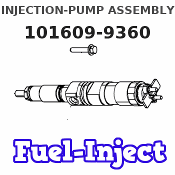
Service parts 101609-9360 INJECTION-PUMP ASSEMBLY:
1.
_


5.
AUTOM. ADVANCE MECHANIS
6.
COUPLING PLATE
8.
_
9.
_
11.
Nozzle and Holder
12.
Open Pre:MPa(Kqf/cm2)
17.7(180)

15.
NOZZLE SET
Cross reference number
BOSCH
F 01G 09U 1HV
f01g09u1hv
ZEXEL
101609-9360
1016099360
MITSUBISHI-HEAV
3436511010
3436511010
Zexel num
Bosch num
Firm num
Name
101609-9360
F 01G 09U 1HV
3436511010 MITSUBISHI-HEAV
INJECTION-PUMP ASSEMBLY
S6K-T K
S6K-T K
Calibration Data:
Adjustment conditions
Test oil
1404 Test oil ISO4113 or {SAEJ967d}
1404 Test oil ISO4113 or {SAEJ967d}
Test oil temperature
degC
40
40
45
Nozzle and nozzle holder
105780-8140
Bosch type code
EF8511/9A
Nozzle
105780-0000
Bosch type code
DN12SD12T
Nozzle holder
105780-2080
Bosch type code
EF8511/9
Opening pressure
MPa
17.2
Opening pressure
kgf/cm2
175
Injection pipe
Outer diameter - inner diameter - length (mm) mm 6-2-600
Outer diameter - inner diameter - length (mm) mm 6-2-600
Overflow valve
131424-5720
Overflow valve opening pressure
kPa
255
221
289
Overflow valve opening pressure
kgf/cm2
2.6
2.25
2.95
Tester oil delivery pressure
kPa
255
255
255
Tester oil delivery pressure
kgf/cm2
2.6
2.6
2.6
Direction of rotation (viewed from drive side)
Right R
Right R
Injection timing adjustment
Direction of rotation (viewed from drive side)
Right R
Right R
Injection order
1-5-3-6-
2-4
Pre-stroke
mm
3.55
3.5
3.6
Rack position
After adjusting injection quantity. R=A
After adjusting injection quantity. R=A
Beginning of injection position
Drive side NO.1
Drive side NO.1
Difference between angles 1
Cal 1-5 deg. 60 59.5 60.5
Cal 1-5 deg. 60 59.5 60.5
Difference between angles 2
Cal 1-3 deg. 120 119.5 120.5
Cal 1-3 deg. 120 119.5 120.5
Difference between angles 3
Cal 1-6 deg. 180 179.5 180.5
Cal 1-6 deg. 180 179.5 180.5
Difference between angles 4
Cyl.1-2 deg. 240 239.5 240.5
Cyl.1-2 deg. 240 239.5 240.5
Difference between angles 5
Cal 1-4 deg. 300 299.5 300.5
Cal 1-4 deg. 300 299.5 300.5
Injection quantity adjustment
Adjusting point
A
Rack position
9.8
Pump speed
r/min
900
900
900
Average injection quantity
mm3/st.
120.5
119.5
121.5
Max. variation between cylinders
%
0
-2.5
2.5
Basic
*
Fixing the lever
*
Injection quantity adjustment_02
Adjusting point
C
Rack position
5.8+-0.5
Pump speed
r/min
500
500
500
Average injection quantity
mm3/st.
9.5
8.2
10.8
Max. variation between cylinders
%
0
-14
14
Fixing the rack
*
Injection quantity adjustment_03
Adjusting point
D
Rack position
10++
Pump speed
r/min
100
100
100
Average injection quantity
mm3/st.
125
125
130
Fixing the lever
*
Rack limit
*
Test data Ex:
Governor adjustment
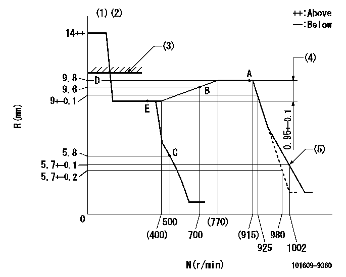
N:Pump speed
R:Rack position (mm)
(1)Target notch: K
(2)Tolerance for racks not indicated: +-0.05mm.
(3)RACK LIMIT
(4)Rack difference between N = N1 and N = N2
(5)Set idle sub-spring
----------
K=5 N1=900r/min N2=350r/min
----------
----------
K=5 N1=900r/min N2=350r/min
----------
Speed control lever angle
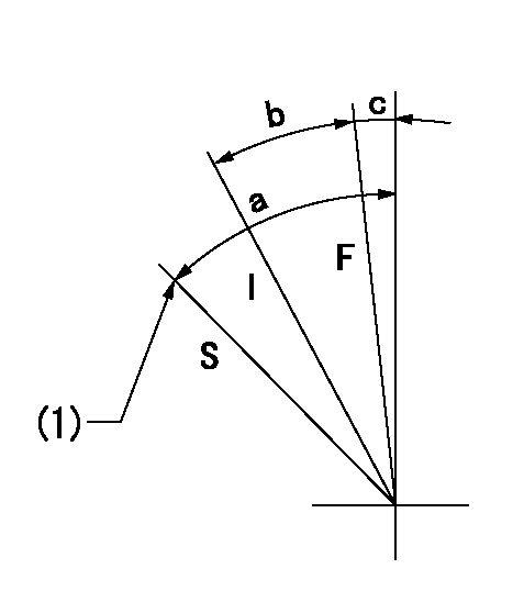
F:Full speed
I:Idle
S:Stop
(1)Stopper bolt setting
----------
----------
a=31deg+-3deg b=12deg+-5deg c=6deg+-5deg
----------
----------
a=31deg+-3deg b=12deg+-5deg c=6deg+-5deg
Stop lever angle
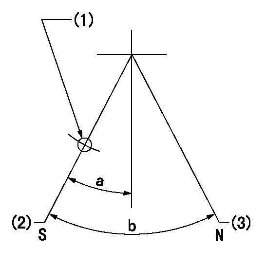
N:Pump normal
S:Stop the pump.
(1)Use the hole at R = aa
(2)Speed = bb, rack position = cc (sealed at delivery)
(3)Normal
----------
aa=25mm bb=0r/min cc=1-0.5mm
----------
a=21deg+-5deg b=(55deg)
----------
aa=25mm bb=0r/min cc=1-0.5mm
----------
a=21deg+-5deg b=(55deg)
0000001501 I/P WITH LOAD PLUNGER ADJ
Load plunger-equipped pump adjustment
1. Adjust the variation between cylinders and the injection quantity.
2. At Full point A, adjust the pre-stroke to the specified value.
3. After pre-stroke adjustment, reconfirm that the fuel injection quantity and the variation between cylinders is as specified.
----------
----------
----------
----------
Timing setting

(1)Pump vertical direction
(2)Position of gear mark '3' at No 1 cylinder's beginning of injection
(3)B.T.D.C.: aa
(4)After adjusting the injection quantity, adjust at rack position bb.
----------
aa=6deg bb=(9.8)mm
----------
a=(110deg)
----------
aa=6deg bb=(9.8)mm
----------
a=(110deg)
Information:
Problem
Some fuel injectors may fail on certain Challenger 75 Tractors and 3176 Truck Engines.
Affected Product
Model & Identification Number
Challenger 75 (4CJ1-406)
3176 (2YG1-Up; 7LG1-4822)
Parts Needed
Use the following parts in quantities needed to perform repairs. The application of each injector listed is noted. Use remanufactured injectors, unless unavailable.
0R3397 Injector Grp. (4P9510 if reman unavailable for 7LG 250-300 HP)0R3398 Injector Grp. (4P9520 if reman unavailable for 7LG 325 HP and 4CJ)0R3399 Injector Grp. (4P9610 if reman unavailable for 2YG 250-275 HP)0R3400 Injector Grp. (4P9620 if reman unavailable for 2YG 300-325 HP)9X7557 Seal (injector upper O-ring)9X7722 Seal (injector lower O-ring)336044 Seal (injector thrust-pad-retaining O-ring)Action Required
1. Isolate the injector which is causing the problem. Some failure modes require duplication of the conditions where the customer say the problem occurs (i.e. at full load, idle, high speed, low speed, etc.)2. Replace injectors only after verifying a problem using the 1U6661 Unit Injector Tester, cutting out cylinders, etc. Replace any failed injectors according to the rework procedures attached.Service Claim Allowances
This is a 2.5-hour job. Add 0.2 hours for 1st injector diagnostic test and 0.1 hours for each additional injector test. Add 1.2 hours for first injector sleeve replaced and 0.7 hours for each additional sleeve replaced.
3176 Truck Engines
Parts Disposition
Handle the parts in accordance with your Warranty Bulletin on warranty parts handling.
Attach. (1-Rework Procedure)Rework Procedure
1. Drain fuel from the cylinder head and fuel manifold. Remove air inlet piping, valve covers and Jake Brake (if equipped) , rocker arm assemblies, and injector hold down bolts. Remove the suspect injector(s) for inspection and test. Mark each injector to denote the cylinder from which it was removed. It is important to install the injector(s) into the same cylinder to prevent combustion gas leaks.2. Test the injector(s) using the 1U6661 Unit Injector Tester. Check for leaks, VOP, and spray pattern. Replace all injectors which do not pass these test.Procedure For Installing The Following Injector Part Numbers:
4P1410, 4P1420, 4P2810, 4P2820, 0R3177, AND 0R3178
1. Inspect the raised edge on the injector cone for signs of damage. If any nicks or dings are present, do not reuse the injector.2. Ream the sleeves before installing the injectors. Ream only until the sleeve has been cut to provide a full length concentric taper past the injector/sleeve sealing interface. Full removal of the indentation created by the cone step edge is not necessary.3. Install new O-rings on the injector and apply STP ® to prevent cutting during installation.4. Install the injectors, apply 6V4876 Molykote to the hold-down bolt threads and tighten the bolts to 33 NM (24 ft. lb.). Make sure the longer 5P8347 Bolts and 4P8525 Spacers (or 8T0100 Bolts and 4P1711 Spacers) are used.5. Inspect bridge assemblies for wear.Procedures For Installing All Other Injectors:
1. Ream the sleeves before installing the injectors. Ream only until the sleeves have been cut to provide a full length concentric taper past the injector/sleeve sealing interface.2. After reaming, apply a thin coating of liquid machinist's blue (Dykem) to the bottom of the sleeves - allow to dry. Install injector without
Have questions with 101609-9360?
Group cross 101609-9360 ZEXEL
Mitsubishi-Heav
Dpico
Mitsubishi-Heav
101609-9360
F 01G 09U 1HV
3436511010
INJECTION-PUMP ASSEMBLY
S6K-T
S6K-T