Information injection-pump assembly
ZEXEL
101609-9224
1016099224
MITSUBISHI-HEAV
3436501054
3436501054

Rating:
Service parts 101609-9224 INJECTION-PUMP ASSEMBLY:
1.
_
5.
AUTOM. ADVANCE MECHANIS
6.
COUPLING PLATE
8.
_
9.
_
11.
Nozzle and Holder
12.
Open Pre:MPa(Kqf/cm2)
17.2(175)/21.6(220)
15.
NOZZLE SET
Cross reference number
ZEXEL
101609-9224
1016099224
MITSUBISHI-HEAV
3436501054
3436501054
Zexel num
Bosch num
Firm num
Name
101609-9224
3436501054 MITSUBISHI-HEAV
INJECTION-PUMP ASSEMBLY
S6K-T K
S6K-T K
Calibration Data:
Adjustment conditions
Test oil
1404 Test oil ISO4113 or {SAEJ967d}
1404 Test oil ISO4113 or {SAEJ967d}
Test oil temperature
degC
40
40
45
Nozzle and nozzle holder
105780-8140
Bosch type code
EF8511/9A
Nozzle
105780-0000
Bosch type code
DN12SD12T
Nozzle holder
105780-2080
Bosch type code
EF8511/9
Opening pressure
MPa
17.2
Opening pressure
kgf/cm2
175
Injection pipe
Outer diameter - inner diameter - length (mm) mm 6-2-600
Outer diameter - inner diameter - length (mm) mm 6-2-600
Overflow valve
131424-5720
Overflow valve opening pressure
kPa
255
221
289
Overflow valve opening pressure
kgf/cm2
2.6
2.25
2.95
Tester oil delivery pressure
kPa
255
255
255
Tester oil delivery pressure
kgf/cm2
2.6
2.6
2.6
Direction of rotation (viewed from drive side)
Right R
Right R
Injection timing adjustment
Direction of rotation (viewed from drive side)
Right R
Right R
Injection order
1-5-3-6-
2-4
Pre-stroke
mm
3.7
3.65
3.75
Rack position
After adjusting injection quantity. R=A
After adjusting injection quantity. R=A
Beginning of injection position
Drive side NO.1
Drive side NO.1
Difference between angles 1
Cal 1-5 deg. 60 59.5 60.5
Cal 1-5 deg. 60 59.5 60.5
Difference between angles 2
Cal 1-3 deg. 120 119.5 120.5
Cal 1-3 deg. 120 119.5 120.5
Difference between angles 3
Cal 1-6 deg. 180 179.5 180.5
Cal 1-6 deg. 180 179.5 180.5
Difference between angles 4
Cyl.1-2 deg. 240 239.5 240.5
Cyl.1-2 deg. 240 239.5 240.5
Difference between angles 5
Cal 1-4 deg. 300 299.5 300.5
Cal 1-4 deg. 300 299.5 300.5
Injection quantity adjustment
Adjusting point
A
Rack position
7.05
Pump speed
r/min
1100
1100
1100
Average injection quantity
mm3/st.
41.5
40.5
42.5
Max. variation between cylinders
%
0
-3.5
3.5
Basic
*
Fixing the lever
*
Injection quantity adjustment_02
Adjusting point
-
Rack position
6.4+-0.5
Pump speed
r/min
425
425
425
Average injection quantity
mm3/st.
8
6.7
9.3
Max. variation between cylinders
%
0
-10
10
Fixing the rack
*
Remarks
Adjust only variation between cylinders; adjust governor according to governor specifications.
Adjust only variation between cylinders; adjust governor according to governor specifications.
Test data Ex:
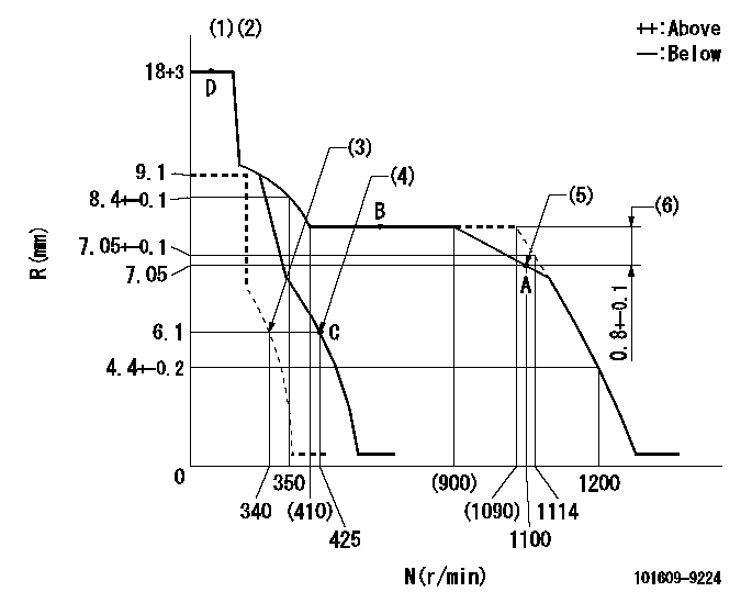
Governor adjustment

N:Pump speed
R:Rack position (mm)
(1)Target notch: K
(2)Tolerance for racks not indicated: +-0.05mm.
(3)Set idle sub-spring
(4)Main spring setting
(5)Set the torque spring.
(6)Rack difference between N = N1 and N = N2
----------
K=15 N1=1100r/min N2=700r/min
----------
----------
K=15 N1=1100r/min N2=700r/min
----------
Speed control lever angle

F:Full speed
I:Idle
(1)Stopper bolt setting
----------
----------
a=19deg+-5deg b=19deg+-5deg
----------
----------
a=19deg+-5deg b=19deg+-5deg
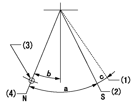
Stop lever angle

N:Pump normal
S:Stop the pump.
(1)Contacts outer boss.
(2)Contacts inner boss.
(3)Use the hole at R = aa
(4)Normal
----------
aa=60mm
----------
a=53deg+-5deg b=26.5deg+-5deg c=(9deg)
----------
aa=60mm
----------
a=53deg+-5deg b=26.5deg+-5deg c=(9deg)
0000001501 I/P WITH LOAD PLUNGER ADJ
Load plunger-equipped pump adjustment
1. Adjust the variation between cylinders and the injection quantity.
2. At Full point A, adjust the pre-stroke to the specified value.
3. After pre-stroke adjustment, reconfirm that the fuel injection quantity and the variation between cylinders is as specified.
----------
----------
----------
----------
Timing setting

(1)Pump vertical direction
(2)Position of gear mark '3' at No 1 cylinder's beginning of injection
(3)B.T.D.C.: aa
(4)After adjusting the injection quantity, adjust at rack position bb.
----------
aa=6deg bb=7.05mm
----------
a=(110deg)
----------
aa=6deg bb=7.05mm
----------
a=(110deg)
Information:
Cooling System
At operating temperature, the engine coolant is hot and under pressure.Steam can cause personal injury.Check the coolant level only after the engine has been stopped and the filler cap is cool enough to touch with your bare hand.Remove the filler cap slowly to relieve pressure.Cooling system conditioner contains alkali. Avoid contact with the skin and eyes to prevent personal injury.Use all cleaning solutions with care.
Never add coolant to an overheated engine, allow the engine to cool first.Check the specific gravity of the antifreeze solution frequently in cold weather to ensure adequate protection.If the machine is to be stored in or shipped to, an area with below freezing temperatures, the cooling system must be protected against freezing to the lowest expected ambient temperature.All water is corrosive at engine operating temperature. The cooling system should be protected with conditioner at all times regardless of the concentration of antifreeze. This can be done by using Caterpillar coolant conditioner elements. Use a precharge element when filling the system or changing coolant. Install a new maintenance element every 250 service hours during operation.
Do not use Caterpillar cooling conditioner elements with Dowtherm 209 Full-Fill coolant. Follow the instructions provided with the Dowtherm 209 Full-Fill coolant.Coolant should be drained and replaced every 2000 service hours or 1 year. However, when coolant conditioner maintenance elements are replaced every 250 service hours as recommended, the drain period can be extended to 4000 service hours or 2 years.Premix antifreeze solution to provide protection to the lowest expected ambient temperature. Pure undiluted antifreeze will freeze at -23°C (-10°F).Use clean water that is low in scale forming mineral. Do not use softened water.Filling at over 20 liters (5 U.S. gallons) per minute can cause air pockets in the cooling system.After draining and refilling the cooling system, run the engine with the filler cap off until the coolant level stabilizes. Add coolant as necessary to fill the system.The engine cooling system is protected to -28°C (-20°F), with permanent-type antifreeze, when shipped from the factory.Operate with a thermostat in the cooling system all year-round. The engine will overheat without a thermostat.Clean the Cooling System
The machine must be level with the bowl lowered, the parking brake applied and the engine stopped and cool. 1. Remove the radiator cap slowly to relieve the pressure. 2. Remove the access cover, located in the engine guard. 3. Remove the drain valve plug (1). Open the valve (2) and allow the coolant to drain.4. Close the drain valve.5. Fill the cooling system with a cleaning solution. Use a commercially available cleaner or 1 kg sodium bisulfate per 38 liters (2 lb per 10 gal) water.6. Start and operate the engine for 1/2hour. Stop the engine and drain the cleaning solution.7. Flush the system, with the engine stopped, with water until draining water is clear.8. Close the drain valve. Fill the system with a neutralizer. Use a commercially available neutralizer or 250 grams sodium carbonate crystals per 38 liters (1/2 lb to 10 gal) water.9. Operate the
Have questions with 101609-9224?
Group cross 101609-9224 ZEXEL
Mitsubishi-Heav
101609-9224
3436501054
INJECTION-PUMP ASSEMBLY
S6K-T
S6K-T
