Information injection-pump assembly
ZEXEL
101609-3870
1016093870
KOMATSU
6736711180
6736711180
Rating:
Cross reference number
ZEXEL
101609-3870
1016093870
KOMATSU
6736711180
6736711180
Zexel num
Bosch num
Firm num
Name
101609-3870
6736711180 KOMATSU
INJECTION-PUMP ASSEMBLY
SA6D102E-
SA6D102E-
Calibration Data:
Adjustment conditions
Test oil
1404 Test oil ISO4113 or {SAEJ967d}
1404 Test oil ISO4113 or {SAEJ967d}
Test oil temperature
degC
40
40
45
Nozzle and nozzle holder
105780-8140
Bosch type code
EF8511/9A
Nozzle
105780-0000
Bosch type code
DN12SD12T
Nozzle holder
105780-2080
Bosch type code
EF8511/9
Opening pressure
MPa
17.2
Opening pressure
kgf/cm2
175
Injection pipe
Outer diameter - inner diameter - length (mm) mm 6-2-600
Outer diameter - inner diameter - length (mm) mm 6-2-600
Overflow valve
131424-3420
Overflow valve opening pressure
kPa
255
221
289
Overflow valve opening pressure
kgf/cm2
2.6
2.25
2.95
Tester oil delivery pressure
kPa
255
255
255
Tester oil delivery pressure
kgf/cm2
2.6
2.6
2.6
Direction of rotation (viewed from drive side)
Right R
Right R
Injection timing adjustment
Direction of rotation (viewed from drive side)
Right R
Right R
Injection order
1-5-3-6-
2-4
Pre-stroke
mm
2.5
2.45
2.55
Beginning of injection position
Drive side NO.1
Drive side NO.1
Difference between angles 1
Cal 1-5 deg. 60 59.5 60.5
Cal 1-5 deg. 60 59.5 60.5
Difference between angles 2
Cal 1-3 deg. 120 119.5 120.5
Cal 1-3 deg. 120 119.5 120.5
Difference between angles 3
Cal 1-6 deg. 180 179.5 180.5
Cal 1-6 deg. 180 179.5 180.5
Difference between angles 4
Cyl.1-2 deg. 240 239.5 240.5
Cyl.1-2 deg. 240 239.5 240.5
Difference between angles 5
Cal 1-4 deg. 300 299.5 300.5
Cal 1-4 deg. 300 299.5 300.5
Injection quantity adjustment
Adjusting point
A
Rack position
9.9
Pump speed
r/min
1175
1175
1175
Average injection quantity
mm3/st.
105
104
106
Max. variation between cylinders
%
0
-2.5
2.5
Basic
*
Fixing the lever
*
Boost pressure
kPa
50.7
50.7
Boost pressure
mmHg
380
380
Hydraulic cylinder ON
*
Injection quantity adjustment_02
Adjusting point
C
Rack position
7.2+-0.5
Pump speed
r/min
400
400
400
Average injection quantity
mm3/st.
14.5
13.5
15.5
Max. variation between cylinders
%
0
-15
15
Fixing the rack
*
Boost pressure
kPa
0
0
0
Boost pressure
mmHg
0
0
0
Hydraulic cylinder ON
*
Injection quantity adjustment_03
Adjusting point
D
Rack position
-
Pump speed
r/min
100
100
100
Average injection quantity
mm3/st.
85
85
95
Fixing the lever
*
Boost pressure
kPa
0
0
0
Boost pressure
mmHg
0
0
0
Hydraulic cylinder OFF
*
Rack limit
*
Boost compensator adjustment
Pump speed
r/min
800
800
800
Rack position
(8.75)
Boost pressure
kPa
18.7
16
21.4
Boost pressure
mmHg
140
120
160
Boost compensator adjustment_02
Pump speed
r/min
800
800
800
Rack position
10.05
Boost pressure
kPa
37.3
37.3
37.3
Boost pressure
mmHg
280
280
280
Test data Ex:
Governor adjustment
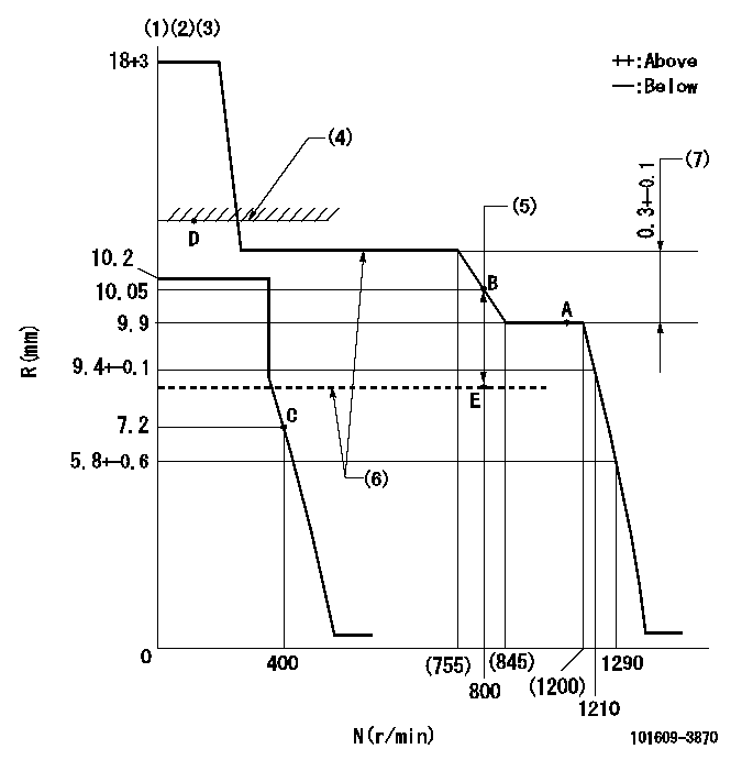
N:Pump speed
R:Rack position (mm)
(1)Target notch: K
(2)Tolerance for racks not indicated: +-0.05mm.
(3)Adjust the secondary timing before adjusting the governor.
(4)RACK LIMIT (When hydraulic cylinder is OFF)
(5)Boost compensator stroke: BCL
(6)When hydraulic cylinder ON: P1
(7)Rack difference between N = N1 and N = N2
----------
K=13 BCL=1.3+-0.1mm P1=392kPa(4kgf/cm2) N1=1175r/min N2=700r/min
----------
----------
K=13 BCL=1.3+-0.1mm P1=392kPa(4kgf/cm2) N1=1175r/min N2=700r/min
----------
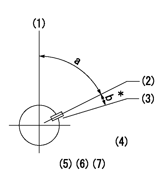
Speed control lever angle
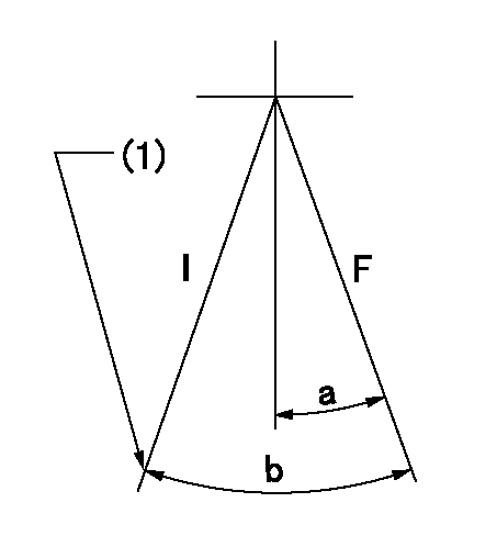
F:Full speed
I:Idle
(1)Stopper bolt setting
----------
----------
a=12deg+-5deg b=29deg+-5deg
----------
----------
a=12deg+-5deg b=29deg+-5deg
Stop lever angle
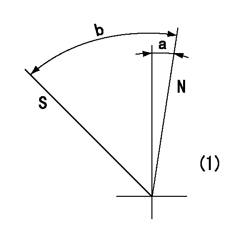
N:Pump normal
S:Stop the pump.
(1)No return spring
----------
----------
a=0deg+-5deg b=53deg+-5deg
----------
----------
a=0deg+-5deg b=53deg+-5deg
Timing setting
(1)Pump vertical direction
(2)Key groove position at No. 1 cylinder's beginning of injection position (at BTDC: aa).
(3)Position of the key groove of the No. 1 cylinder at B.T.D.C. bb (fix the governor flyweight at this position for delivery).
(4)B.T.D.C.: aa
(5)At second timing adjustment, set the camshaft at the * position and tighten the flyweight locknut.
(6)Align the flyweight's timing gear position with the lockpin groove and then fully tighten the flyweight to the camshaft.
(7)Remove the lock pin and adjust the governor. Reinstall the lock pin to fix the flyweight for delivery.
----------
aa=19.5deg bb=0deg
----------
a=54deg54min+-3deg b=9deg45min+-30min
----------
aa=19.5deg bb=0deg
----------
a=54deg54min+-3deg b=9deg45min+-30min
Information:
November 10, 2003
U-307
A-211
D-227
O-256
TT-24
TM-7
Partsstock action only PRODUCT IMPROVEMENT PROGRAM FOR REMOVINGCERTAIN REMAN FUEL INJECTORS FROM DEALER PART STOCK
7750 PI70071
The information supplied in this serviceletter may not be valid after the termination date of this program. Donot perform the work outlined in this Service Letter after the terminationdate without first contacting your Caterpillar product analyst.TERMINATION DATE
February 29, 2004PROBLEM
Certain fuel injectors need to be removed fromdealer part stock. A number of fuel injectors were built with a Valve OpeningPressure (VOP) spacer that missed a hardening operation. This non-hardenedspacer allows premature wear, causing several operational problems whichmay include: engine misfire, low power, white smoke, and engine would notstart.ACTION REQUIRED
Only remove engine injectors within the suspectdate code range from your parts supply.
In order to perform this inspection, injectorsmust be removed from the packaging.
Repackage all injectors.
Illustration 1 (3406E, C15) Illustration 2 (C10, C12)SERVICE CLAIM ALLOWANCES
Submit one claim for all 0R4667, 0R4893, 0R4894,0R4895, 0R9256, 0R9257, 0R9258, 0R9259, 0R9803, 0R4986, 0R4987, 0R4988,0R7549, 0R8773, 0R8780, and 0R9530 removed from parts stock. Remove onlythose injectors from the suspect serial number range listed below. 0R4667, 0R4893, 0R4894, 0R4895, 0R9256,0R9257, 0R9258, 0R9259, and 0R9803 3406E and C15 injectors should be removedif the serial number is between 318224-371662. 0R4986, 0R4987, 0R4988, 0R7549, 0R8773,0R8780, and 0R9530 C10 and C12 injectors should be removed if the serialnumber is between 34768-47935.PARTS DISPOSITION
These remanufactured parts need to be returnedwith dealer normal core returns in order to allow for core deposit refund.
Have questions with 101609-3870?
Group cross 101609-3870 ZEXEL
Komatsu
Komatsu
Komatsu
101609-3870
6736711180
INJECTION-PUMP ASSEMBLY
SA6D102E-
SA6D102E-