Information injection-pump assembly
BOSCH
9 400 615 904
9400615904
ZEXEL
101609-3440
1016093440
KOMATSU
3863813
3863813
Rating:
Include in #2:
104265-3004
as _
Cross reference number
BOSCH
9 400 615 904
9400615904
ZEXEL
101609-3440
1016093440
KOMATSU
3863813
3863813
Zexel num
Bosch num
Firm num
Name
101609-3440
9 400 615 904
3863813 KOMATSU
INJECTION-PUMP ASSEMBLY
S6D102E K 14BE INJECTION PUMP ASSY PE6A PE
S6D102E K 14BE INJECTION PUMP ASSY PE6A PE
101609-3440
9 400 615 904
6735711390 KOMATSU
INJECTION-PUMP ASSEMBLY
S6D102E K 14BE INJECTION PUMP ASSY PE6A PE
S6D102E K 14BE INJECTION PUMP ASSY PE6A PE
Calibration Data:
Adjustment conditions
Test oil
1404 Test oil ISO4113 or {SAEJ967d}
1404 Test oil ISO4113 or {SAEJ967d}
Test oil temperature
degC
40
40
45
Nozzle and nozzle holder
105780-8140
Bosch type code
EF8511/9A
Nozzle
105780-0000
Bosch type code
DN12SD12T
Nozzle holder
105780-2080
Bosch type code
EF8511/9
Opening pressure
MPa
17.2
Opening pressure
kgf/cm2
175
Injection pipe
Outer diameter - inner diameter - length (mm) mm 6-2-600
Outer diameter - inner diameter - length (mm) mm 6-2-600
Overflow valve
131424-3420
Overflow valve opening pressure
kPa
255
221
289
Overflow valve opening pressure
kgf/cm2
2.6
2.25
2.95
Tester oil delivery pressure
kPa
157
157
157
Tester oil delivery pressure
kgf/cm2
1.6
1.6
1.6
Direction of rotation (viewed from drive side)
Right R
Right R
Injection timing adjustment
Direction of rotation (viewed from drive side)
Right R
Right R
Injection order
1-5-3-6-
2-4
Pre-stroke
mm
2.5
2.45
2.55
Beginning of injection position
Drive side NO.1
Drive side NO.1
Difference between angles 1
Cal 1-5 deg. 60 59.5 60.5
Cal 1-5 deg. 60 59.5 60.5
Difference between angles 2
Cal 1-3 deg. 120 119.5 120.5
Cal 1-3 deg. 120 119.5 120.5
Difference between angles 3
Cal 1-6 deg. 180 179.5 180.5
Cal 1-6 deg. 180 179.5 180.5
Difference between angles 4
Cyl.1-2 deg. 240 239.5 240.5
Cyl.1-2 deg. 240 239.5 240.5
Difference between angles 5
Cal 1-4 deg. 300 299.5 300.5
Cal 1-4 deg. 300 299.5 300.5
Injection quantity adjustment
Adjusting point
A
Rack position
9.7
Pump speed
r/min
1125
1125
1125
Average injection quantity
mm3/st.
73
72
74
Max. variation between cylinders
%
0
-2.5
2.5
Basic
*
Fixing the lever
*
Boost pressure
kPa
31.3
31.3
Boost pressure
mmHg
255
255
Hydraulic cylinder ON
*
Injection quantity adjustment_02
Adjusting point
C
Rack position
8.4+-0.5
Pump speed
r/min
375
375
375
Average injection quantity
mm3/st.
10.5
9.5
11.5
Max. variation between cylinders
%
0
-15
15
Fixing the rack
*
Boost pressure
kPa
0
0
0
Boost pressure
mmHg
0
0
0
Hydraulic cylinder ON
*
Injection quantity adjustment_03
Adjusting point
D
Rack position
-
Pump speed
r/min
100
100
100
Average injection quantity
mm3/st.
70
70
80
Fixing the lever
*
Boost pressure
kPa
0
0
0
Boost pressure
mmHg
0
0
0
Hydraulic cylinder OFF
*
Rack limit
*
Boost compensator adjustment
Pump speed
r/min
800
800
800
Rack position
R1-0.2
Boost pressure
kPa
13.3
10.6
16
Boost pressure
mmHg
100
80
120
Boost compensator adjustment_02
Pump speed
r/min
800
800
800
Rack position
R1(9.7)
Boost pressure
kPa
18
18
18
Boost pressure
mmHg
135
135
135
Test data Ex:
Governor adjustment
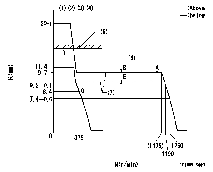
N:Pump speed
R:Rack position (mm)
(1)Target notch: K
(2)Tolerance for racks not indicated: +-0.05mm.
(3)The torque control spring does not operate.
(4)Adjust the secondary timing before adjusting the governor.
(5)RACK LIMIT (When hydraulic cylinder is OFF)
(6)Boost compensator stroke: BCL
(7)When hydraulic cylinder ON: P1
----------
K=12 BCL=0.2+-0.1mm P1=((392)kPa,(4)kgf/cm2)
----------
----------
K=12 BCL=0.2+-0.1mm P1=((392)kPa,(4)kgf/cm2)
----------
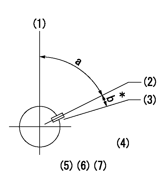
Speed control lever angle
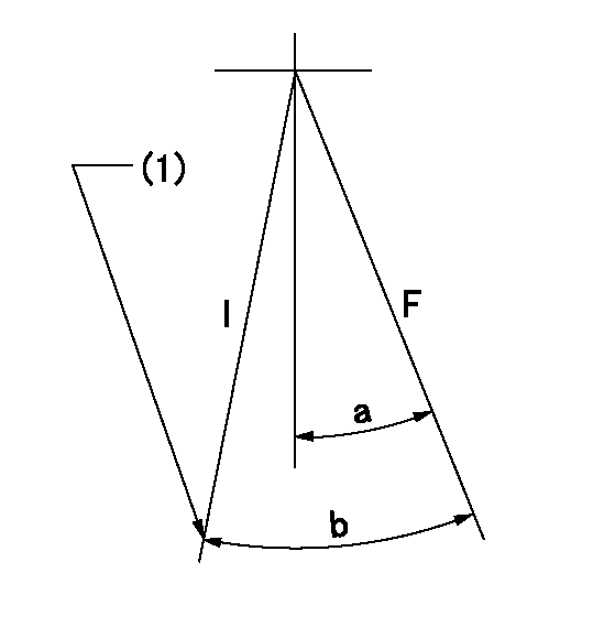
F:Full speed
I:Idle
(1)Stopper bolt setting
----------
----------
a=18deg+-5deg b=23deg+-5deg
----------
----------
a=18deg+-5deg b=23deg+-5deg
Stop lever angle
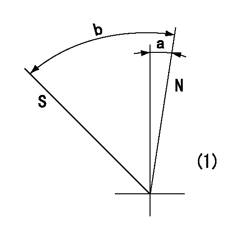
N:Pump normal
S:Stop the pump.
(1)No return spring
----------
----------
a=0deg+-5deg b=53deg+-5deg
----------
----------
a=0deg+-5deg b=53deg+-5deg
Timing setting
(1)Pump vertical direction
(2)Key groove position at No. 1 cylinder's beginning of injection position (at BTDC: aa).
(3)Position of the key groove of the No. 1 cylinder at B.T.D.C. bb (fix the governor flyweight at this position for delivery).
(4)B.T.D.C.: aa
(5)At second timing adjustment, set the camshaft at the * position and tighten the flyweight locknut.
(6)Align the flyweight's timing gear position with the lockpin groove and then fully tighten the flyweight to the camshaft.
(7)Remove the lock pin and adjust the governor. Reinstall the lock pin to fix the flyweight for delivery.
----------
aa=18deg bb=0deg
----------
a=54deg54min+-3deg b=9deg+-30min
----------
aa=18deg bb=0deg
----------
a=54deg54min+-3deg b=9deg+-30min
Information:
Cut apart used filters to see contaminants. Use a 6V790S FilterCutter
to cut the filter housing.
Maintenance for Engines Using Heavy Fuel
Engines operating on heavy fuel must be carefully monitored and maintained.Service intervals must be strictly observed. Operators must be trained toperform a thorough service inspection.
"As Needed" Periodic Activities
Test fuel as it is delivered. Identify contaminant levels immediately and notify appropriate operations personnel.
Before storage, test for compatibility between fuel in the tanks and the fuel being purchased. Keep the fuel in separate tanks if possible.
Use regular S.O.S oil analysis to determine if there are wear particles in the oil, and maintain the proper TBN level.
Request infrared analysis on used oils to determine the effects of burning heavy fuel on the crankcase oil.
Daily Activities
Maintain and monitor fuel treatment equipment.
Record engine temperatures to assure adequate jacket water temperature, aftercooler temperature, and air intake temperature.
If equipped with a turbocharger water wash attachment, wash the turbocharger exhaust turbine. It is necessary to remove deposits from the turbine side of the turbocharger. (A washer attachment which does this is available on 3600 Family Engines.)
Check exhaust thermocouples and record exhaust temperatures. Be alert for worn exhaust valves.
Measure valve stem projection when new; use a stationary point such asthe valve cover gasket surface for a reference point. Record the measurementsfor each valve for later follow-up measurements. If valve stem projection movesmore than 1.25 mm (.050 in.) consider disassembly to find the reason. Anotherway to observe valve face wear is to measure and record changes on valve lashover a period of time.
Monitor fuel and oil filter differentials every shift. Check for filter plugging.
Drain settling and fuel tank bottoms daily. Take note if there is excessive water or sediment.
Every 1000 Hours
Check one cylinder head for exhaust valve seating and carbon build-up. Check the fuel injectors for adequate nozzle spray pattern. Make sure the valve rotators are operating.
Clean the turbocharger (exhaust turbine) (3500 and 3600 Family Engines without washers).
Operating the Engine at Low Load
If you're expecting to operate your engine at part load for extendedperiods, switch to No.2 diesel fuel or marine diesel oil. (Make sure the fuelinjectors are not run without fuel during the switch.)
The following chart shows the relationship between engine load and length oftime. It will guide you on what type of fuel to burn in light load applications.
Chart with time and numbers.
Other Heavy Fuel Tips
Here are some things to keep in mind when using heavy fuels.
Cut apart used filters to see contaminants. As contamination levels increase, the quality of diesel fuel is generally decreasing.
As fuel quality decreases, it becomes even more important to have good fuel treatment systems. The treatment system can sometimes compensate for poor fuel quality. ..but there is less margin for error with a system that is not working correctly.
Often, diesel engines cannot operate on fuel that is straight from the fuel tank (bunkered).
Viscosity does not relate to quality. Do not use fuel thickness
Have questions with 101609-3440?
Group cross 101609-3440 ZEXEL
Komatsu
Komatsu
101609-3440
9 400 615 904
3863813
INJECTION-PUMP ASSEMBLY
S6D102E
S6D102E
101609-3440
9 400 615 904
6735711390
INJECTION-PUMP ASSEMBLY
S6D102E
S6D102E