Information injection-pump assembly
ZEXEL
101609-3390
1016093390

Rating:
Service parts 101609-3390 INJECTION-PUMP ASSEMBLY:
1.
_

5.
AUTOM. ADVANCE MECHANIS
6.
COUPLING PLATE
7.
COUPLING PLATE
8.
_
9.
_
10.
NOZZLE AND HOLDER ASSY
11.
Nozzle and Holder
12.
Open Pre:MPa(Kqf/cm2)
23.5{240}
13.
NOZZLE-HOLDER
14.
NOZZLE
15.
NOZZLE SET
Include in #1:
101609-3390
as INJECTION-PUMP ASSEMBLY
Include in #2:
104265-3040
as _
Cross reference number
ZEXEL
101609-3390
1016093390
Zexel num
Bosch num
Firm num
Name
101609-3390
INJECTION-PUMP ASSEMBLY
Calibration Data:
Adjustment conditions
Test oil
1404 Test oil ISO4113 or {SAEJ967d}
1404 Test oil ISO4113 or {SAEJ967d}
Test oil temperature
degC
40
40
45
Nozzle and nozzle holder
105780-8140
Bosch type code
EF8511/9A
Nozzle
105780-0000
Bosch type code
DN12SD12T
Nozzle holder
105780-2080
Bosch type code
EF8511/9
Opening pressure
MPa
17.2
Opening pressure
kgf/cm2
175
Injection pipe
Outer diameter - inner diameter - length (mm) mm 6-2-600
Outer diameter - inner diameter - length (mm) mm 6-2-600
Overflow valve
131424-3420
Overflow valve opening pressure
kPa
255
221
289
Overflow valve opening pressure
kgf/cm2
2.6
2.25
2.95
Tester oil delivery pressure
kPa
157
157
157
Tester oil delivery pressure
kgf/cm2
1.6
1.6
1.6
Direction of rotation (viewed from drive side)
Right R
Right R
Injection timing adjustment
Direction of rotation (viewed from drive side)
Right R
Right R
Injection order
1-5-3-6-
2-4
Pre-stroke
mm
2.5
2.45
2.55
Beginning of injection position
Drive side NO.1
Drive side NO.1
Difference between angles 1
Cal 1-5 deg. 60 59.5 60.5
Cal 1-5 deg. 60 59.5 60.5
Difference between angles 2
Cal 1-3 deg. 120 119.5 120.5
Cal 1-3 deg. 120 119.5 120.5
Difference between angles 3
Cal 1-6 deg. 180 179.5 180.5
Cal 1-6 deg. 180 179.5 180.5
Difference between angles 4
Cyl.1-2 deg. 240 239.5 240.5
Cyl.1-2 deg. 240 239.5 240.5
Difference between angles 5
Cal 1-4 deg. 300 299.5 300.5
Cal 1-4 deg. 300 299.5 300.5
Injection quantity adjustment
Adjusting point
A
Rack position
10.8
Pump speed
r/min
900
900
900
Average injection quantity
mm3/st.
100
99
101
Max. variation between cylinders
%
0
-2.5
2.5
Basic
*
Fixing the rack
*
Injection quantity adjustment_02
Adjusting point
C
Rack position
8.3+-0.5
Pump speed
r/min
410
410
410
Average injection quantity
mm3/st.
11.5
10.5
12.5
Max. variation between cylinders
%
0
-15
15
Fixing the rack
*
Injection quantity adjustment_03
Adjusting point
E
Rack position
-
Pump speed
r/min
100
100
100
Average injection quantity
mm3/st.
115
115
125
Fixing the lever
*
Rack limit
*
Test data Ex:
Governor adjustment

N:Pump speed
R:Rack position (mm)
(1)Target notch: K
(2)Tolerance for racks not indicated: +-0.05mm.
(3)Adjust the secondary timing before adjusting the governor.
(4)RACK LIMIT
(5)Stop lever at stopping (with the speed lever at full)
(6)Set idle sub-spring
----------
K=8
----------
----------
K=8
----------
Speed control lever angle
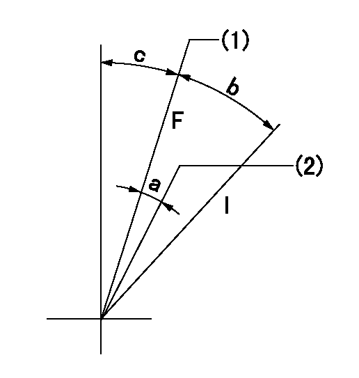
F:Full speed
I:Idle
(1)Set the pump speed at aa. ( At delivery )
(2)Set the pump speed at bb.
----------
aa=900r/min bb=750r/min
----------
a=(5deg)+-5deg b=(18deg)+-5deg c=(1deg)+-5deg
----------
aa=900r/min bb=750r/min
----------
a=(5deg)+-5deg b=(18deg)+-5deg c=(1deg)+-5deg
Stop lever angle
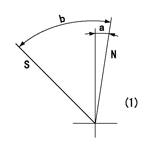
N:Pump normal
S:Stop the pump.
(1)No return spring
----------
----------
a=0deg+-5deg b=53deg+-5deg
----------
----------
a=0deg+-5deg b=53deg+-5deg
Timing setting
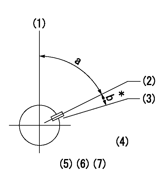
(1)Pump vertical direction
(2)Key groove position at No. 1 cylinder's beginning of injection position (at BTDC: aa).
(3)Position of the key groove of the No. 1 cylinder at B.T.D.C. bb (fix the governor flyweight at this position for delivery).
(4)B.T.D.C.: aa
(5)At second timing adjustment, set the camshaft at the * position and tighten the flyweight locknut.
(6)Align the flyweight's timing gear position with the lockpin groove and then fully tighten the flyweight to the camshaft.
(7)Remove the lock pin and adjust the governor. Reinstall the lock pin to fix the flyweight for delivery.
----------
aa=16deg bb=0deg
----------
a=54deg54min+-3deg b=8deg+-30min
----------
aa=16deg bb=0deg
----------
a=54deg54min+-3deg b=8deg+-30min
Information:
(1) Bore in bearing of idler gear ... 28.600 0.048 mm (1.1260 .0019 in) Diameter of shaft for the idler gear ... 28.512 0.013 mm (1.1225 .0005 in)Clearance between bearing and shaft ... 0.028 to 0.150 mm (.0011 to .0059 in)(2) Clearance between gear and body of pump ... 0.05 to 0.66 mm (.002 to .026 in)(3) Diameter of shafts for pump ... 22.217 0.005 mm (.8747 .0002 in) Bore in bearings for shafts ... 22.286 0.051 mm (.8774 .0020 in)Clearance between shafts and bearings ... 0.013 to 0.125 mm (.0005 to .0049 in)(4) Depth that bearings are installed in pump bodies ... 1.52 0.25 mm (.060 .010 in)(5) Gear. Length of gears ... 50.808 0.025 mm (2.0003 .0010 in) Depth of bore in pump body for gears ... 50.935 0.020 mm (2.0053 .0008 in)Clearance between end of gears and pump body ... 0.081 to 0.173 mm (.0032 to .0068 in)(6) Length of gears ... 38.070 0.025 mm (1.4988 .0010 in) Depth of bore in pump body for gears ... 38.197 0.020 mm (1.5038 .0008 in)Clearance between end of gears and pump body ... 0.081 to 0.173 mm (.0032 to .0068 in)(7) Distance from the end of idler shafts to gear faces ... 21.03 0.13 mm (.828 .005 in) Maximum temperature of gear when shrinking in place ... 398°C (750°F)(8) Distance from the end of the drive shaft to gear face ... 38.23 0.13 mm (1.505 .005 in) Maximum temperature of gear when shrinking in place ... 398°C (750°F)(9) Torque for bolt holding drive gear to drive shaft ... 47 9 N m (35 7 lb ft) Install the bearings in the cover and body for the oil pump so the bearing junctions (joints) are in the position shown (30 15 degrees from centerline).(10) Distance dowel extends from body ... 4.1 0.5 mm (.16 .02 in)(11) Shaft assembly. Distance shaft assembly extends from body ... 30.50 0.25 mm (1.200 .010 in) Before running, lubricate pump with oil. Pump must rotate freely by hand.
Have questions with 101609-3390?
Group cross 101609-3390 ZEXEL
Komatsu
Komatsu
Komatsu
Komatsu
Komatsu
Komatsu
Komatsu
101609-3390
INJECTION-PUMP ASSEMBLY