Information injection-pump assembly
ZEXEL
101609-3380
1016093380
Rating:
Service parts 101609-3380 INJECTION-PUMP ASSEMBLY:
1.
_
5.
AUTOM. ADVANCE MECHANIS
6.
COUPLING PLATE
7.
COUPLING PLATE
8.
_
9.
_
10.
NOZZLE AND HOLDER ASSY
11.
Nozzle and Holder
12.
Open Pre:MPa(Kqf/cm2)
23.5{240}
13.
NOZZLE-HOLDER
14.
NOZZLE
15.
NOZZLE SET
Include in #1:
101609-3380
as INJECTION-PUMP ASSEMBLY
Include in #2:
104258-5213
as _
Cross reference number
ZEXEL
101609-3380
1016093380
Zexel num
Bosch num
Firm num
Name
101609-3380
INJECTION-PUMP ASSEMBLY
Calibration Data:
Adjustment conditions
Test oil
1404 Test oil ISO4113 or {SAEJ967d}
1404 Test oil ISO4113 or {SAEJ967d}
Test oil temperature
degC
40
40
45
Nozzle and nozzle holder
105780-8140
Bosch type code
EF8511/9A
Nozzle
105780-0000
Bosch type code
DN12SD12T
Nozzle holder
105780-2080
Bosch type code
EF8511/9
Opening pressure
MPa
17.2
Opening pressure
kgf/cm2
175
Injection pipe
Outer diameter - inner diameter - length (mm) mm 6-2-600
Outer diameter - inner diameter - length (mm) mm 6-2-600
Overflow valve
131424-3420
Overflow valve opening pressure
kPa
255
221
289
Overflow valve opening pressure
kgf/cm2
2.6
2.25
2.95
Tester oil delivery pressure
kPa
157
157
157
Tester oil delivery pressure
kgf/cm2
1.6
1.6
1.6
Direction of rotation (viewed from drive side)
Right R
Right R
Injection timing adjustment
Direction of rotation (viewed from drive side)
Right R
Right R
Injection order
1-5-3-6-
2-4
Pre-stroke
mm
2.5
2.45
2.55
Beginning of injection position
Drive side NO.1
Drive side NO.1
Difference between angles 1
Cal 1-5 deg. 60 59.5 60.5
Cal 1-5 deg. 60 59.5 60.5
Difference between angles 2
Cal 1-3 deg. 120 119.5 120.5
Cal 1-3 deg. 120 119.5 120.5
Difference between angles 3
Cal 1-6 deg. 180 179.5 180.5
Cal 1-6 deg. 180 179.5 180.5
Difference between angles 4
Cyl.1-2 deg. 240 239.5 240.5
Cyl.1-2 deg. 240 239.5 240.5
Difference between angles 5
Cal 1-4 deg. 300 299.5 300.5
Cal 1-4 deg. 300 299.5 300.5
Injection quantity adjustment
Adjusting point
A
Rack position
9.1
Pump speed
r/min
750
750
750
Average injection quantity
mm3/st.
92
91
93
Max. variation between cylinders
%
0
-2.5
2.5
Basic
*
Fixing the rack
*
Injection quantity adjustment_02
Adjusting point
C
Rack position
6.7+-0.5
Pump speed
r/min
400
400
400
Average injection quantity
mm3/st.
12.5
11.5
13.5
Max. variation between cylinders
%
0
-15
15
Fixing the rack
*
Injection quantity adjustment_03
Adjusting point
D
Rack position
-
Pump speed
r/min
100
100
100
Average injection quantity
mm3/st.
110
110
120
Fixing the lever
*
Rack limit
*
Test data Ex:
Governor adjustment
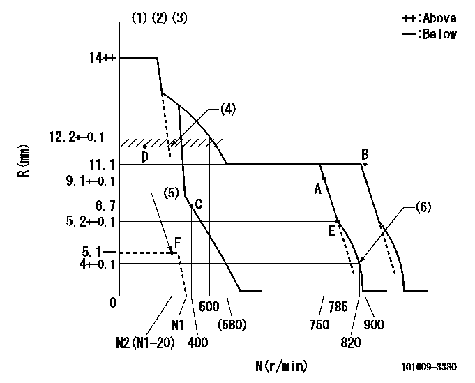
N:Pump speed
R:Rack position (mm)
(1)Target notch: K
(2)Tolerance for racks not indicated: +-0.05mm.
(3)Adjust the secondary timing before adjusting the governor.
(4)RACK LIMIT
(5)Stop lever at stopping (with the speed lever at full)
(6)Set idle sub-spring
----------
K=4
----------
----------
K=4
----------
Speed control lever angle
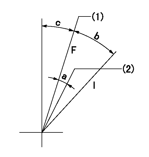
F:Full speed
I:Idle
(1)Set the pump speed at aa. ( At delivery )
(2)Set the pump speed at bb.
----------
aa=900r/min bb=750r/min
----------
a=5deg+-5deg b=19deg+-5deg c=4deg+-5deg
----------
aa=900r/min bb=750r/min
----------
a=5deg+-5deg b=19deg+-5deg c=4deg+-5deg
Stop lever angle
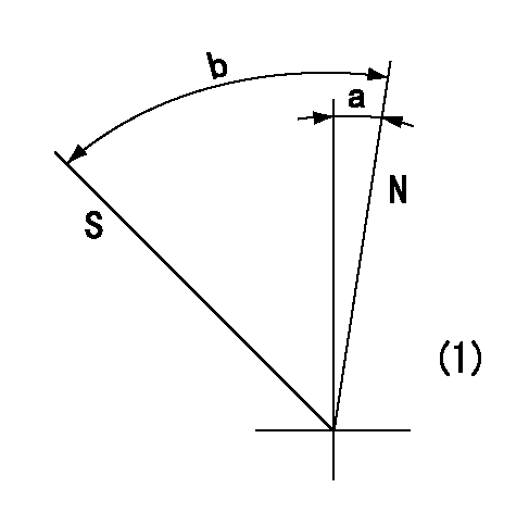
N:Pump normal
S:Stop the pump.
(1)No return spring
----------
----------
a=0deg+-5deg b=53deg+-5deg
----------
----------
a=0deg+-5deg b=53deg+-5deg
Timing setting
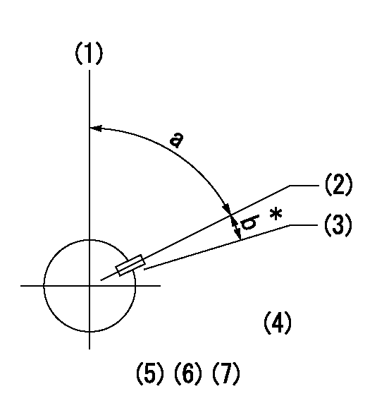
(1)Pump vertical direction
(2)Key groove position at No. 1 cylinder's beginning of injection position (at BTDC: aa).
(3)Position of the key groove of the No. 1 cylinder at B.T.D.C. bb (fix the governor flyweight at this position for delivery).
(4)B.T.D.C.: aa
(5)At second timing adjustment, set the camshaft at the * position and tighten the flyweight locknut.
(6)Align the flyweight's timing gear position with the lockpin groove and then fully tighten the flyweight to the camshaft.
(7)Remove the lock pin and adjust the governor. Reinstall the lock pin to fix the flyweight for delivery.
----------
aa=17deg bb=0deg
----------
a=54deg54min+-3deg b=8.5deg+-30min
----------
aa=17deg bb=0deg
----------
a=54deg54min+-3deg b=8.5deg+-30min
Information:
Illustration 23. (2) 141-6737 Adjustable Microgauge.
(7) Top of the 3P-1542 Barrel. (8) 141-6727 Calibration Pump Assembly.1. Place the 141-6737 Adjustable Microgauge on top of the 3P-1542 Barrel of the 141-6727 Calibration Pump Assembly.2. When starting to torque 124-5932 Lever Assemblies, the difference between the face of the 141-6730 Plunger and the 2N-2658 Bolt is about 0.03 mm (.001 in). By setting the 141-6737 Adjustable Microgauge (2) on top of the 141-6727 Calibration Pump Assembly (8), the 141-6737 Plunger can be positioned 25.40 mm (.001 in) above the face of the 3P-1542 Barrel (7).
Illustration 24. (9) 2N-2658 Bolt. (10) 124-5940 Shutoff Lever.3. As the 2N-2658 Bolt (9) is torqued, the 141-6730 Plunger will move down flush with the 3P-1542 Barrel (7) or will be very close to being flush. The calibration can begin from this point. The 2N-2658 Bolts must freely turn in and out of the 124-5940 Shutoff Levers (10) because the calibration depends on where the head of the 2N-2658 Bolt (9) first begins to clamp the 124-5940 Shutoff Lever for the starting point of the calibration.End Play Adjustment
1. In order to save time, use two torque wrenches (color-coding is convenient for distinguishing between the two wrenches). Set one torque wrench to 1.7 N m (15 lb in) and the second torque wrench to N m (35 lb in).
Illustration 25. (1) 124-5941 Shaft. (2) 4N-1826 Dowel on one end of the HSMFS Injection Pump Group. (3) 126-7232 Dowels.2. Adjust the end play in the 124-5941 Shaft. The SMFS 109-0324 Governor And Fuel Injection Pump Group had the dowel in the middle of the sleeve and a large amount of end play in the shaft was acceptable. Now that the 126-7232 Dowels (3) are between two 124-5934 Sleeves, the amount of end play is important. It is necessary that an adjustment be performed to minimize the amount of end play in the 124-5941 Shaft (1).3. The 126-7232 Dowels (3) are located between two 124-5934 Sleeves. Set the 126-7232 Dowels between 0.25 to 0.40 mm (.010 to .016 in) by tapping in the 4N-1826 Dowels (2) until the desired end play is achieved.* With the 1.7 N m (15 lb in) torque wrench, torque the 2N-2658 Bolts to 1.7 N m (15 lb in).* Then use the 4 N m (35 lb in) torque wrench to torque the 2N-2658 Bolts to 3.4 N m (30 lb in) in order to calibrate within specifications.Calibrating the 124-5932 Lever Assemblies.
Illustration 26. Calibrating the 124-5932 Lever Assemblies.
(1) 2N-2658 Bolts. (2) 124-5940 Shutoff Lever.1. Begin with the first 2N-2658 Bolt (1) and turn it until it just begins to clamp (feels snug) on the 124-5940 Shutoff Lever (2).2. Move to the other side and turn the second 2N-2658 Bolt (1) until just begins to clamp (feels snug).* Alternate between sides and tighten each 2N-2658 Bolt about 15 degrees each time.
Illustration 27. View of the HSMFS Injection Pump Group.
(3) Top of the 141-6730 Plunger shown flush with the 3P-1542 Barrel (4).3. Continue until the torque
Have questions with 101609-3380?
Group cross 101609-3380 ZEXEL
Komatsu
Komatsu
Komatsu
Komatsu
Komatsu
Komatsu
101609-3380
INJECTION-PUMP ASSEMBLY
