Information injection-pump assembly
BOSCH
9 400 611 608
9400611608
ZEXEL
101609-3362
1016093362
KOMATSU
3863595
3863595
Rating:
Service parts 101609-3362 INJECTION-PUMP ASSEMBLY:
1.
_

5.
AUTOM. ADVANCE MECHANIS
6.
COUPLING PLATE
7.
COUPLING PLATE
8.
_
9.
_
10.
NOZZLE AND HOLDER ASSY
11.
Nozzle and Holder
12.
Open Pre:MPa(Kqf/cm2)
21.6{220}
13.
NOZZLE-HOLDER
14.
NOZZLE
15.
NOZZLE SET
Include in #1:
101609-3362
as INJECTION-PUMP ASSEMBLY
Include in #2:
104258-5182
as _
Cross reference number
BOSCH
9 400 611 608
9400611608
ZEXEL
101609-3362
1016093362
KOMATSU
3863595
3863595
Zexel num
Bosch num
Firm num
Name
101609-3362
9 400 611 608
3863595 KOMATSU
INJECTION-PUMP ASSEMBLY
S6D102E K 14BE INJECTION PUMP ASSY PE6A PE
S6D102E K 14BE INJECTION PUMP ASSY PE6A PE
101609-3362
9 400 611 608
6735711240 KOMATSU
INJECTION-PUMP ASSEMBLY
S6D102E K 14BE INJECTION PUMP ASSY PE6A PE
S6D102E K 14BE INJECTION PUMP ASSY PE6A PE
Calibration Data:
Adjustment conditions
Test oil
1404 Test oil ISO4113 or {SAEJ967d}
1404 Test oil ISO4113 or {SAEJ967d}
Test oil temperature
degC
40
40
45
Nozzle and nozzle holder
105780-8140
Bosch type code
EF8511/9A
Nozzle
105780-0000
Bosch type code
DN12SD12T
Nozzle holder
105780-2080
Bosch type code
EF8511/9
Opening pressure
MPa
17.2
Opening pressure
kgf/cm2
175
Injection pipe
Outer diameter - inner diameter - length (mm) mm 6-2-600
Outer diameter - inner diameter - length (mm) mm 6-2-600
Overflow valve
131424-3420
Overflow valve opening pressure
kPa
255
221
289
Overflow valve opening pressure
kgf/cm2
2.6
2.25
2.95
Tester oil delivery pressure
kPa
157
157
157
Tester oil delivery pressure
kgf/cm2
1.6
1.6
1.6
Direction of rotation (viewed from drive side)
Right R
Right R
Injection timing adjustment
Direction of rotation (viewed from drive side)
Right R
Right R
Injection order
1-5-3-6-
2-4
Pre-stroke
mm
2.5
2.45
2.55
Beginning of injection position
Drive side NO.1
Drive side NO.1
Difference between angles 1
Cal 1-5 deg. 60 59.5 60.5
Cal 1-5 deg. 60 59.5 60.5
Difference between angles 2
Cal 1-3 deg. 120 119.5 120.5
Cal 1-3 deg. 120 119.5 120.5
Difference between angles 3
Cal 1-6 deg. 180 179.5 180.5
Cal 1-6 deg. 180 179.5 180.5
Difference between angles 4
Cyl.1-2 deg. 240 239.5 240.5
Cyl.1-2 deg. 240 239.5 240.5
Difference between angles 5
Cal 1-4 deg. 300 299.5 300.5
Cal 1-4 deg. 300 299.5 300.5
Injection quantity adjustment
Adjusting point
A
Rack position
9.4
Pump speed
r/min
1250
1250
1250
Average injection quantity
mm3/st.
92
91
93
Max. variation between cylinders
%
0
-2.5
2.5
Basic
*
Fixing the lever
*
Boost pressure
kPa
50.7
50.7
Boost pressure
mmHg
380
380
Hydraulic cylinder ON
*
Injection quantity adjustment_02
Adjusting point
-
Rack position
7+-0.5
Pump speed
r/min
400
400
400
Average injection quantity
mm3/st.
10
9
11
Max. variation between cylinders
%
0
-15
15
Fixing the rack
*
Boost pressure
kPa
0
0
0
Boost pressure
mmHg
0
0
0
Hydraulic cylinder ON
*
Remarks
Adjust only variation between cylinders; adjust governor according to governor specifications.
Adjust only variation between cylinders; adjust governor according to governor specifications.
Injection quantity adjustment_03
Adjusting point
D
Rack position
-
Pump speed
r/min
100
100
100
Average injection quantity
mm3/st.
80
80
90
Fixing the lever
*
Boost pressure
kPa
0
0
0
Boost pressure
mmHg
0
0
0
Hydraulic cylinder OFF
*
Rack limit
*
Boost compensator adjustment
Pump speed
r/min
800
800
800
Rack position
R1-1.25
Boost pressure
kPa
13.3
10.6
16
Boost pressure
mmHg
100
80
120
Boost compensator adjustment_02
Pump speed
r/min
800
800
800
Rack position
R1(9.4)
Boost pressure
kPa
37.3
37.3
37.3
Boost pressure
mmHg
280
280
280
Test data Ex:
Governor adjustment
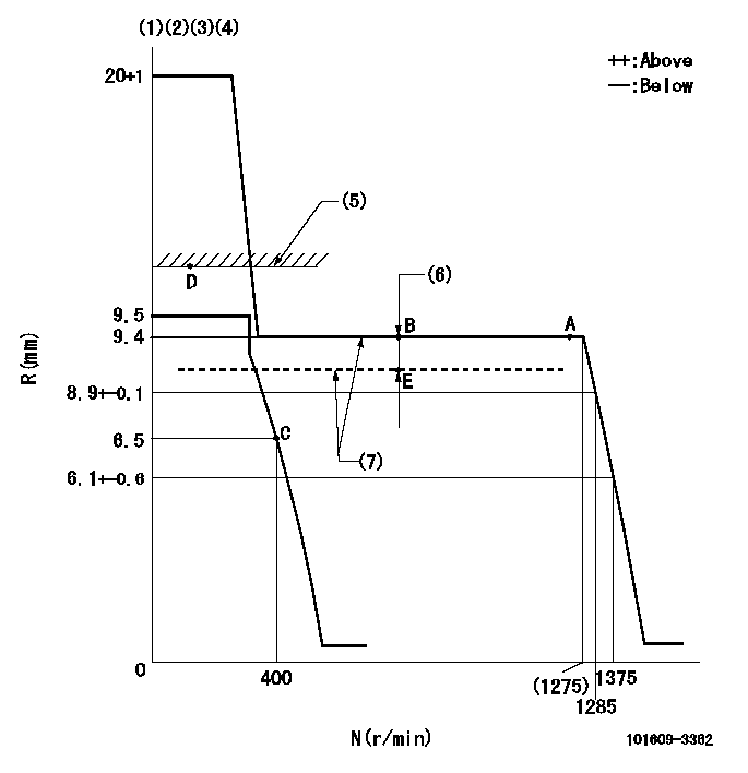
N:Pump speed
R:Rack position (mm)
(1)Target notch: K
(2)Tolerance for racks not indicated: +-0.05mm.
(3)The torque control spring does not operate.
(4)Adjust the secondary timing before adjusting the governor.
(5)RACK LIMIT (When hydraulic cylinder is OFF)
(6)Boost compensator stroke: BCL
(7)When hydraulic cylinder ON: P1
----------
K=17 BCL=1.25+-0.1mm P1=((392)kPa{(4)kgf/cm2})
----------
----------
K=17 BCL=1.25+-0.1mm P1=((392)kPa{(4)kgf/cm2})
----------
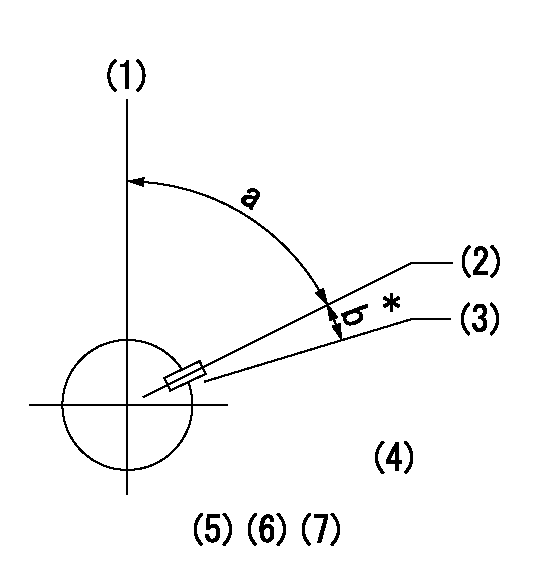
Speed control lever angle
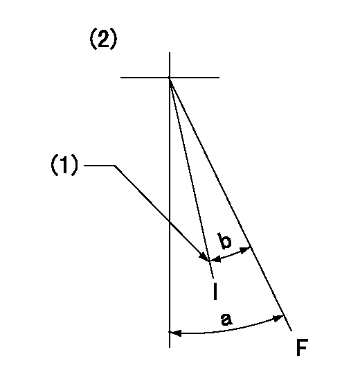
F:Full speed
I:Idle
(1)Stopper bolt setting
(2)Use the center hole at R = aa
----------
aa=80mm
----------
a=49deg+-3deg b=29deg+-5deg
----------
aa=80mm
----------
a=49deg+-3deg b=29deg+-5deg
Stop lever angle
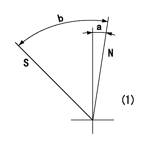
N:Pump normal
S:Stop the pump.
(1)No return spring
----------
----------
a=0deg+-5deg b=53deg+-5deg
----------
----------
a=0deg+-5deg b=53deg+-5deg
Timing setting
(1)Pump vertical direction
(2)Key groove position at No. 1 cylinder's beginning of injection position (at BTDC: aa).
(3)Position of the key groove of the No. 1 cylinder at B.T.D.C. bb (fix the governor flyweight at this position for delivery).
(4)B.T.D.C.: aa
(5)At second timing adjustment, set the camshaft at the * position and tighten the flyweight locknut.
(6)Align the flyweight's timing gear position with the lockpin groove and then fully tighten the flyweight to the camshaft.
(7)Remove the lock pin and adjust the governor. Reinstall the lock pin to fix the flyweight for delivery.
----------
aa=18deg bb=0deg
----------
a=54deg54min+-3deg b=9deg+-30min
----------
aa=18deg bb=0deg
----------
a=54deg54min+-3deg b=9deg+-30min
Information:
(1) Fuel pump adapter assembly diameter ... 88.864 to 88.887 mm (3.4986 to 3.4995 in.) Bore diameter in cylinder block for fuel pump adapter assembly and upper thrust collar ... 88.90 to 88.936 mm (3.500 to 3.5014 in.)Clearance of adapter assembly in cylinder block ... 0.013 to 0.071 mm (.0005 to .0028 in.)(2) Inside diameter of bushing in adapter assembly ... 47.625 to 47.666 mm (1.8750 to 1.8766 in.) Upper fuel pump drive shaft diameter ... 47.533 to 47.574 mm (1.8714 to 1.8730 in.)Clearance of drive shaft in adapter assembly bushing ... 0.05 to 0.132 mm (.002 to .0052 in.)(3) Outside diameter of upper thrust collar ... 88.80 to 88.85 mm (3.496 to 3.498 in.) Clearance of upper thrust collar in block ... 0.05 to 0.137 mm (.002 to .0054 in.)Inside diameter of upper thrust collar ... 47.90 to 48.01 mm (1.886 to 1.890 in.)Clearance of fuel pump drive shaft in thrust collar ... 0.33 to 0.472 mm (.013 to .0186 in.)Width of groove in upper thrust collar ... 2.431 to 2.456 mm (.0957 to .0967 in.)(4) Upper thrust collar sealing ring thickness ... 2.357 to 2.383 mm (.0928 to .0938 in.) Clearance of sealing ring in groove ... 0.048 to 0.099 mm (.0019 to .0039 in.)(5) Bore diameter in cylinder block for lower thrust bearing ... 57.127 to 57.147 mm (2.2491 to 2.2499 in.) Lower thrust bearing bore diameter for bushing ... 45.242 to 45.283 mm (1.7812 to 1.7828 in.)(6) Outer diameter of bushing ... 45.321 to 45.357 mm (1.7843 to 1.7857 in.) Interference fit of bushing in lower thrust bearing ... 0.038 to 0.114 mm (.0015 to .0045 in.)Inside diameter of bushing (after reaming) ... 41.288 to 41.316 mm (1.6255 to 1.6266 in.)Lower diameter of fuel pump drive shaft ... 41.184 to 41.209 mm (1.6214 to 1.6224 in.)Clearance of fuel pump drive shaft in bushing ... 0.079 to 0.132 mm (.0031 to .0052 in.)(7) Auxiliary drive shaft rear bushing: Outside diameter of bushing ... 35.778 to 35.827 mm (1.4086 to 1.4105 in.)Bore diameter in cylinder block for rear bushing ... 35.720 to 35.753 mm (1.4063 to 1.4076 in.)Interference fit of bushing in cylinder block ... 0.03 to 0.107 mm (.001 to .0042 in.)Inside diameter of installed bushing ... 31.75 to 31.799 mm (1.25 to 1.2519 in.)Running clearance of auxiliary drive shaft in bushing ... 0.03 to 0.099 mm (.001 to .0039 in.)(8) Torque for auxiliary drive shaft gear bolts ... 30 N m (22 lb.ft.)(9) Auxiliary drive shaft gear bore diameter ... 25.40 to 25.43 mm (1.000 to 1.001 in.)(10) Auxiliary drive shaft thrust washers: Thickness ... 4.763 to 4.839 mm (.1875 to .1905 in.)Cylinder block recess depth for thrust washer ... 4.67 to 4.75 mm (.184 to .187 in.)Projection of thrust washer above cylinder block front face ... 0.013 to 0.18 mm (.0005 to .007 in.)Outside
Have questions with 101609-3362?
Group cross 101609-3362 ZEXEL
Komatsu
Komatsu
Komatsu
Komatsu
Komatsu
101609-3362
9 400 611 608
3863595
INJECTION-PUMP ASSEMBLY
S6D102E
S6D102E
101609-3362
9 400 611 608
6735711240
INJECTION-PUMP ASSEMBLY
S6D102E
S6D102E