Information injection-pump assembly
BOSCH
9 400 615 891
9400615891
ZEXEL
101609-3130
1016093130
KOMATSU
6209721420
6209721420

Rating:
Service parts 101609-3130 INJECTION-PUMP ASSEMBLY:
1.
_
5.
AUTOM. ADVANCE MECHANIS
6.
COUPLING PLATE
7.
COUPLING PLATE
8.
_
9.
_
11.
Nozzle and Holder
6209-11-3100
12.
Open Pre:MPa(Kqf/cm2)
22.1{225}

15.
NOZZLE SET
Include in #1:
101609-3130
as INJECTION-PUMP ASSEMBLY
Include in #2:
104257-3021
as _
Cross reference number
BOSCH
9 400 615 891
9400615891
ZEXEL
101609-3130
1016093130
KOMATSU
6209721420
6209721420
Zexel num
Bosch num
Firm num
Name
101609-3130
9 400 615 891
6209721420 KOMATSU
INJECTION-PUMP ASSEMBLY
SA6D95L K 14BE INJECTION PUMP ASSY PE6A PE
SA6D95L K 14BE INJECTION PUMP ASSY PE6A PE
Calibration Data:
Adjustment conditions
Test oil
1404 Test oil ISO4113 or {SAEJ967d}
1404 Test oil ISO4113 or {SAEJ967d}
Test oil temperature
degC
40
40
45
Nozzle and nozzle holder
105780-8140
Bosch type code
EF8511/9A
Nozzle
105780-0000
Bosch type code
DN12SD12T
Nozzle holder
105780-2080
Bosch type code
EF8511/9
Opening pressure
MPa
17.2
Opening pressure
kgf/cm2
175
Injection pipe
Outer diameter - inner diameter - length (mm) mm 6-2-600
Outer diameter - inner diameter - length (mm) mm 6-2-600
Overflow valve
131424-7420
Overflow valve opening pressure
kPa
255
221
289
Overflow valve opening pressure
kgf/cm2
2.6
2.25
2.95
Tester oil delivery pressure
kPa
157
157
157
Tester oil delivery pressure
kgf/cm2
1.6
1.6
1.6
Direction of rotation (viewed from drive side)
Right R
Right R
Injection timing adjustment
Direction of rotation (viewed from drive side)
Right R
Right R
Injection order
1-5-3-6-
2-4
Pre-stroke
mm
3.2
3.15
3.25
Beginning of injection position
Drive side NO.1
Drive side NO.1
Difference between angles 1
Cal 1-5 deg. 60 59.5 60.5
Cal 1-5 deg. 60 59.5 60.5
Difference between angles 2
Cal 1-3 deg. 120 119.5 120.5
Cal 1-3 deg. 120 119.5 120.5
Difference between angles 3
Cal 1-6 deg. 180 179.5 180.5
Cal 1-6 deg. 180 179.5 180.5
Difference between angles 4
Cyl.1-2 deg. 240 239.5 240.5
Cyl.1-2 deg. 240 239.5 240.5
Difference between angles 5
Cal 1-4 deg. 300 299.5 300.5
Cal 1-4 deg. 300 299.5 300.5
Injection quantity adjustment
Adjusting point
A
Rack position
10.2
Pump speed
r/min
1150
1150
1150
Average injection quantity
mm3/st.
81.5
80.5
82.5
Max. variation between cylinders
%
0
-2.5
2.5
Basic
*
Fixing the lever
*
Boost pressure
kPa
36
36
Boost pressure
mmHg
270
270
Injection quantity adjustment_02
Adjusting point
-
Rack position
7.3+-0.5
Pump speed
r/min
500
500
500
Average injection quantity
mm3/st.
12.5
11.5
13.5
Max. variation between cylinders
%
0
-15
15
Fixing the rack
*
Boost pressure
kPa
0
0
0
Boost pressure
mmHg
0
0
0
Remarks
Adjust only variation between cylinders; adjust governor according to governor specifications.
Adjust only variation between cylinders; adjust governor according to governor specifications.
Injection quantity adjustment_03
Adjusting point
E
Rack position
12.5+0.2
Pump speed
r/min
100
100
100
Average injection quantity
mm3/st.
90
80
100
Fixing the lever
*
Boost pressure
kPa
0
0
0
Boost pressure
mmHg
0
0
0
Rack limit
*
Boost compensator adjustment
Pump speed
r/min
750
750
750
Rack position
R1-1.6
Boost pressure
kPa
6.7
6.7
6.7
Boost pressure
mmHg
50
50
50
Boost compensator adjustment_02
Pump speed
r/min
750
750
750
Rack position
R1(10.2)
Boost pressure
kPa
25.3
21.3
29.3
Boost pressure
mmHg
190
160
220
Test data Ex:
Governor adjustment
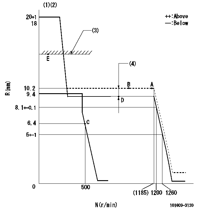
N:Pump speed
R:Rack position (mm)
(1)Target notch: K
(2)Tolerance for racks not indicated: +-0.05mm.
(3)RACK LIMIT: RAL
(4)Boost compensator stroke: BCL
----------
K=13 RAL=12.5+0.2mm BCL=1.6+-0.1mm
----------
----------
K=13 RAL=12.5+0.2mm BCL=1.6+-0.1mm
----------
Speed control lever angle
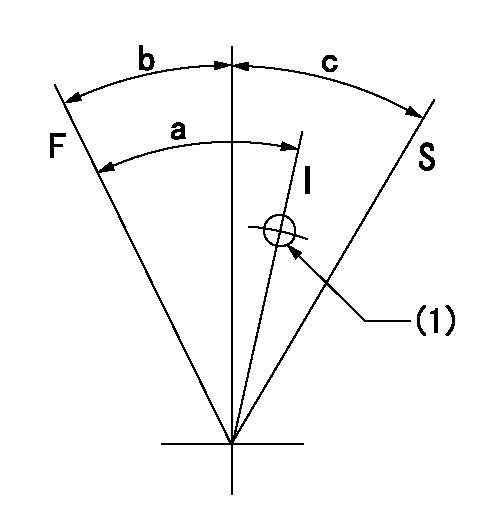
F:Full speed
I:Idle
S:Stop
(1)Use the hole at R = aa
----------
aa=80mm
----------
a=35deg+-5deg b=20deg+-3deg c=32deg+-3deg
----------
aa=80mm
----------
a=35deg+-5deg b=20deg+-3deg c=32deg+-3deg
Timing setting

(1)Pump vertical direction
(2)Position of key groove at No 1 cylinder's beginning of injection
(3)Stamp aligning marks on the pump housing flange.
(4)-
----------
----------
a=58deg+-3deg b=2deg+-30min
----------
----------
a=58deg+-3deg b=2deg+-30min
Information:
Lubrication For A Rebuilt Engine
It is very important for a rebuilt engine to have "adequate" (needed) lubrication during the first seconds of operation. A "dry start" (without needed lubrication) on a rebuilt engine can cause bearing damage.When an engine is rebuilt with new parts, oil is put on each part as it is installed This is generally enough lubrication for engine start-up. However, this lubrication may not be enough or may be lost if the rebuilt engine is place in storage for any length of time.When a factory assembled short block assembly is installed, the oil used at the factory has to give this needed lubrication. However, the factory oil application can flow off the parts in a short block during storage or shipment. As a result the parts in a rebuit engine will not have "adequate" lubrication start-up.To prevent the possibility of a "dry start" and bearing damage during the first seconds of running, use the 1P540; Flow Checking Tool Group, and Shop air pressure to pressure lubricate (fill the main oil passage with oil under pressure) all rebuilt engines.Procedure for Pressure Lubrication
1. Clean the tank of the 1P540 Flow Checking Tool Group thoroughly, and set the pressure regulator to 35 5 psi (240 35 kPa).
Air pressure should not be more than 50 psi (345 kPa) at any time.
2. Put approximately one gallon of engine oil in the tank.
PRESSURE LUBRICATION (Using the 1P540 Flow Checking Tool Group)3. Connect the tools to the engine as shown. The tap shown is connected to the main oil passage.4. Add air pressure to the tank, with the regulator set at 35 5 psi (240 35 kPa). Although the tank does have a hand pump, it is difficult to get enough air pressure to do the job with the hand pump. Therefore, use of shop air is recommended.5. Let the one gallon of engine oil flow into the oil passage under pressure.When filling the crankcase, put in one gallon of oil less than the recommendation in the Lubrication and Maintenance Guides, if engine has received this pressure lubrication application. Also if the engine is not going to be used for a long time, do the above procedure again before the first starting.If shop air is not available for charging the tank, the hand pump may be used to get the minimum required pressure.
Do not use the same 1P540 Flow Checking Tool Group for both "pressure lubrication application" and for checking fuel flow. Incorrect cleaning is probable if the tool is used for both fuel and lube oil. Even a minute amount of dirt in the fuel system can cause fuel nozzle failure.
Dynamometer Test Precaution
To avoid possible engine damage while testing on a dynamometer, the thermostats must be installed and the shunt line connected as shown.
SHUNT LINE CONNECTED TO ENGINEInitial Operation After Engine Reconditioning
The quality of oil control components used in Caterpillar engines is such that, following engine reconditioning (with Caterpillar Service Parts), only an initial operational check is
Have questions with 101609-3130?
Group cross 101609-3130 ZEXEL
Komatsu
101609-3130
9 400 615 891
6209721420
INJECTION-PUMP ASSEMBLY
SA6D95L
SA6D95L