Information injection-pump assembly
BOSCH
9 400 615 890
9400615890
ZEXEL
101609-3120
1016093120
KOMATSU
6221711270
6221711270

Rating:
Include in #2:
104257-3013
as _
Cross reference number
BOSCH
9 400 615 890
9400615890
ZEXEL
101609-3120
1016093120
KOMATSU
6221711270
6221711270
Zexel num
Bosch num
Firm num
Name
101609-3120
9 400 615 890
6221711270 KOMATSU
INJECTION-PUMP ASSEMBLY
S6D108 K
S6D108 K
Calibration Data:
Adjustment conditions
Test oil
1404 Test oil ISO4113 or {SAEJ967d}
1404 Test oil ISO4113 or {SAEJ967d}
Test oil temperature
degC
40
40
45
Nozzle and nozzle holder
105780-8140
Bosch type code
EF8511/9A
Nozzle
105780-0000
Bosch type code
DN12SD12T
Nozzle holder
105780-2080
Bosch type code
EF8511/9
Opening pressure
MPa
17.2
Opening pressure
kgf/cm2
175
Injection pipe
Outer diameter - inner diameter - length (mm) mm 6-2-600
Outer diameter - inner diameter - length (mm) mm 6-2-600
Overflow valve
131424-1520
Overflow valve opening pressure
kPa
157
123
191
Overflow valve opening pressure
kgf/cm2
1.6
1.25
1.95
Tester oil delivery pressure
kPa
157
157
157
Tester oil delivery pressure
kgf/cm2
1.6
1.6
1.6
Direction of rotation (viewed from drive side)
Right R
Right R
Injection timing adjustment
Direction of rotation (viewed from drive side)
Right R
Right R
Injection order
1-5-3-6-
2-4
Pre-stroke
mm
3.6
3.55
3.65
Beginning of injection position
Drive side NO.1
Drive side NO.1
Difference between angles 1
Cal 1-5 deg. 60 59.5 60.5
Cal 1-5 deg. 60 59.5 60.5
Difference between angles 2
Cal 1-3 deg. 120 119.5 120.5
Cal 1-3 deg. 120 119.5 120.5
Difference between angles 3
Cal 1-6 deg. 180 179.5 180.5
Cal 1-6 deg. 180 179.5 180.5
Difference between angles 4
Cyl.1-2 deg. 240 239.5 240.5
Cyl.1-2 deg. 240 239.5 240.5
Difference between angles 5
Cal 1-4 deg. 300 299.5 300.5
Cal 1-4 deg. 300 299.5 300.5
Injection quantity adjustment
Adjusting point
A
Rack position
10.2
Pump speed
r/min
1190
1190
1190
Average injection quantity
mm3/st.
84
83
85
Max. variation between cylinders
%
0
-2
2
Basic
*
Fixing the lever
*
Boost pressure
kPa
50.7
50.7
Boost pressure
mmHg
380
380
Injection quantity adjustment_02
Adjusting point
B
Rack position
6.3+-0.5
Pump speed
r/min
405
405
405
Average injection quantity
mm3/st.
12.5
11.3
13.7
Max. variation between cylinders
%
0
-10
10
Fixing the rack
*
Boost pressure
kPa
0
0
0
Boost pressure
mmHg
0
0
0
Injection quantity adjustment_03
Adjusting point
D
Rack position
15+0.2
Pump speed
r/min
100
100
100
Average injection quantity
mm3/st.
200
190
210
Fixing the lever
*
Boost pressure
kPa
0
0
0
Boost pressure
mmHg
0
0
0
Rack limit
*
Boost compensator adjustment
Pump speed
r/min
750
750
750
Rack position
9.1
Boost pressure
kPa
4
1.3
6.7
Boost pressure
mmHg
30
10
50
Boost compensator adjustment_02
Pump speed
r/min
750
750
750
Rack position
10.7
Boost pressure
kPa
37.3
30.6
44
Boost pressure
mmHg
280
230
330
Test data Ex:
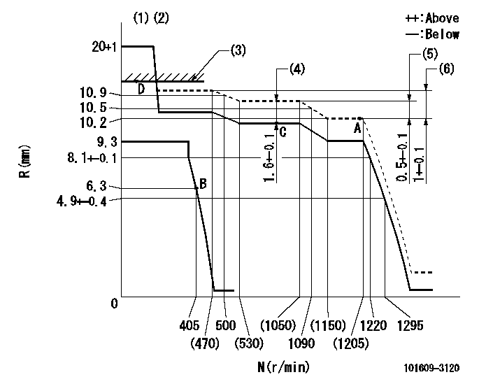
Governor adjustment

N:Pump speed
R:Rack position (mm)
(1)Target notch: K
(2)Tolerance for racks not indicated: +-0.05mm.
(3)RACK LIMIT: RAL
(4)Boost compensator stroke
(5)Rack difference between N = N1 and N = N2
(6)Rack difference between N = N3 and N = N4
----------
K=13 RAL=15+0.2mm N1=1190r/min N2=800r/min N3=1190r/min N4=350r/min
----------
----------
K=13 RAL=15+0.2mm N1=1190r/min N2=800r/min N3=1190r/min N4=350r/min
----------
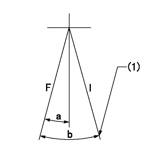
Speed control lever angle

F:Full speed
I:Idle
(1)Stopper bolt setting
----------
----------
a=18deg+-5deg b=31deg+-5deg
----------
----------
a=18deg+-5deg b=31deg+-5deg
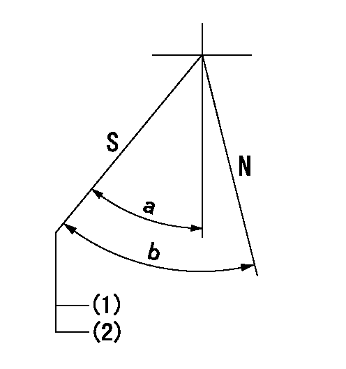
Stop lever angle

N:Pump normal
S:Stop the pump.
(1)Pump speed aa and rack position bb (to be sealed at delivery)
(2)Stopper bolt setting
----------
aa=0r/min bb=1-0.2mm
----------
a=42.5deg+-5deg b=(55deg)
----------
aa=0r/min bb=1-0.2mm
----------
a=42.5deg+-5deg b=(55deg)
Timing setting

(1)Pump vertical direction
(2)Position of camshaft's key groove at No 1 cylinder's beginning of injection
(3)-
(4)-
----------
----------
a=(50deg)
----------
----------
a=(50deg)
Information:
Camshaft
When reconditioning an engine, check the diameter of the camshaft bearing journals and the camshaft lobe height.Camshaft bearing journals have a diameter of 2.5000 .0005 in. (63.500 0.013 mm) and the minimum diameter worn is 2.4970 in. (63.424 mm).To find lobe lift (A) of camshaft, use the following procedure:1. Measure lobe height (B) of one exhaust and one intake lobe.2. Measure base circle (C) of one exhaust and one intake lobe.3. Subtract base circle (C) dimension (STEP 2) from lobe height (B) dimension (STEP 1). The difference is actual lobe lift (A).4. The specified (new) lobe lift (A) is: (a) Exhaust lobe ... .3071 in.(7.800 mm)(b) Intake lobe ... .3077 in.(7.816 mm)5. The maximum permissible difference between actual lobe lift (STEP 3) and specified lobe lift (STEP 4) is .025 in. (0.64 mm).
CAMSHAFT LOBE
A. Lobe lift. B. Lobe height. C. Base circle.With camshaft installed in the cylinder block, check end play. End play with new components should be .007 .003 in. (0.18 0.08 mm). The maximum permissible end play is .020 in. (0.51 mm).Camshaft Followers
Use an 8S2293 Magnet to remove the cam followers.
REMOVING CAM FOLLOWERSCam followers establish a wear pattern with the camshaft lobes. Identify and reinstall the followers removed. Dishing or circular wear pattern is allowed on the cam follower face, providing the wear face keeps a polished appearance. Replace the follower if the wear face is rough or shows signs of scuffing. A new follower can be used with an old camshaft, providing the lobe is in good condition. Put engine oil on the cam followers and the camshaft lobes before installing the cam followers. Use new cam followers with a new camshaft.Camshaft Gears
1. Remove screw (1) and washer (2) from end of camshaft.
REMOVING TIMING ADVANCE RETAINING SCREW
1. Screw. 2. Washer.2. Remove timing advance unit from the camshaft.3. Install puller (A), with spacer (C) over the shaft in the camshaft spacer (B) on spacer (C) as shown and remove the gear from the camshaft.
REMOVING GEAR (Typical Example)
A. 1P2321 Puller. B. 8S5579 Spacer. C. 9S9155 Spacer.To install the gear use the following procedure:1. Heat the gear to a temperature of approximately 400°F (204°C) before installing on the camshaft.
Do not heat the gear with a torch. Do not heat the gear to a temperature of more than 600°F (315°C). Heating the gear with a torch or to a temperature of more than 600°F (315°C) may cause the two drive dowels for the automatic timing advance to loosen and come out of the gear.
2. Align slot in gear hub with the pin in the camshaft. Install the gear on the camshaft with timing mark on gear aligned with timing mark on crankshaft gear. Be sure the gear is completly seated against the shoulder of the camshaft.
Do not drive the gear on the camshaft.
3. Align holes in weights with dowels in gear and install the automatic timing advance.4. Align pin (3) in washer with hole (4) in camshaft and install washer (2).5. Install screw (1) and
Have questions with 101609-3120?
Group cross 101609-3120 ZEXEL
Komatsu
101609-3120
9 400 615 890
6221711270
INJECTION-PUMP ASSEMBLY
S6D108
S6D108