Information injection-pump assembly
BOSCH
F 01G 09U 069
f01g09u069
ZEXEL
101608-9940
1016089940
NISSAN-DIESEL
16713Z6915
16713z6915
Rating:
Include in #2:
104115-1030
as _
Cross reference number
BOSCH
F 01G 09U 069
f01g09u069
ZEXEL
101608-9940
1016089940
NISSAN-DIESEL
16713Z6915
16713z6915
Zexel num
Bosch num
Firm num
Name
Calibration Data:
Adjustment conditions
Test oil
1404 Test oil ISO4113 or {SAEJ967d}
1404 Test oil ISO4113 or {SAEJ967d}
Test oil temperature
degC
40
40
45
Nozzle and nozzle holder
105780-8310
Nozzle
105780-0120
Bosch type code
1 688 901 990
Nozzle holder
105780-2240
Opening pressure
MPa
18
Opening pressure
kgf/cm2
184
Injection pipe
Outer diameter - inner diameter - length (mm) mm 6-2-600
Outer diameter - inner diameter - length (mm) mm 6-2-600
Overflow valve
134424-4120
Overflow valve opening pressure
kPa
255
221
289
Overflow valve opening pressure
kgf/cm2
2.6
2.25
2.95
Tester oil delivery pressure
kPa
255
255
255
Tester oil delivery pressure
kgf/cm2
2.6
2.6
2.6
Direction of rotation (viewed from drive side)
Left L
Left L
Injection timing adjustment
Direction of rotation (viewed from drive side)
Left L
Left L
Injection order
1-4-2-6-
3-5
Pre-stroke
mm
3.5
3.45
3.55
Beginning of injection position
Governor side NO.1
Governor side NO.1
Difference between angles 1
Cal 1-4 deg. 60 59.5 60.5
Cal 1-4 deg. 60 59.5 60.5
Difference between angles 2
Cyl.1-2 deg. 120 119.5 120.5
Cyl.1-2 deg. 120 119.5 120.5
Difference between angles 3
Cal 1-6 deg. 180 179.5 180.5
Cal 1-6 deg. 180 179.5 180.5
Difference between angles 4
Cal 1-3 deg. 240 239.5 240.5
Cal 1-3 deg. 240 239.5 240.5
Difference between angles 5
Cal 1-5 deg. 300 299.5 300.5
Cal 1-5 deg. 300 299.5 300.5
Injection quantity adjustment
Adjusting point
-
Rack position
12
Pump speed
r/min
700
700
700
Average injection quantity
mm3/st.
48.3
46.3
50.3
Max. variation between cylinders
%
0
-3.5
3.5
Basic
*
Fixing the rack
*
Standard for adjustment of the maximum variation between cylinders
*
Injection quantity adjustment_02
Adjusting point
Z
Rack position
9.5+-0.5
Pump speed
r/min
330
330
330
Average injection quantity
mm3/st.
9
8
10
Max. variation between cylinders
%
0
-10
10
Fixing the rack
*
Standard for adjustment of the maximum variation between cylinders
*
Injection quantity adjustment_03
Adjusting point
A
Rack position
R1(13.9)
Pump speed
r/min
1350
1350
1350
Average injection quantity
mm3/st.
60
59
61
Basic
*
Fixing the lever
*
Injection quantity adjustment_04
Adjusting point
B
Rack position
R1-1.9
Pump speed
r/min
700
700
700
Average injection quantity
mm3/st.
48.3
44.3
52.3
Fixing the lever
*
Injection quantity adjustment_05
Adjusting point
I
Rack position
-
Pump speed
r/min
100
100
100
Average injection quantity
mm3/st.
150
150
160
Fixing the lever
*
Rack limit
*
Timer adjustment
Pump speed
r/min
-
Advance angle
deg.
1.5
1
2
Remarks
Measure the actual speed.
Measure the actual speed.
Timer adjustment_02
Pump speed
r/min
-
Advance angle
deg.
6
5.7
6.3
Remarks
Measure the actual speed, stop
Measure the actual speed, stop
Test data Ex:
Governor adjustment
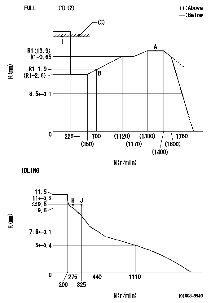
N:Pump speed
R:Rack position (mm)
(1)Torque cam stamping: T1
(2)Tolerance for racks not indicated: +-0.05mm.
(3)RACK LIMIT
----------
T1=N25
----------
----------
T1=N25
----------
Speed control lever angle

F:Full speed
I:Idle
(1)Use the hole at R = aa
(2)Stopper bolt set position 'H'
----------
aa=39mm
----------
a=5deg+-5deg b=41deg+-3deg
----------
aa=39mm
----------
a=5deg+-5deg b=41deg+-3deg
Stop lever angle
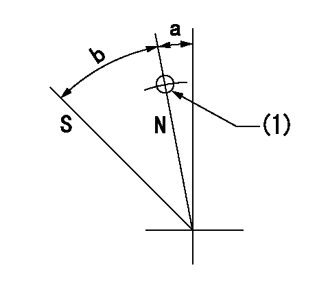
N:Pump normal
S:Stop the pump.
(1)Use the pin at R = aa
----------
aa=42mm
----------
a=5deg+-5deg b=40deg+-5deg
----------
aa=42mm
----------
a=5deg+-5deg b=40deg+-5deg
0000001501 RACK SENSOR
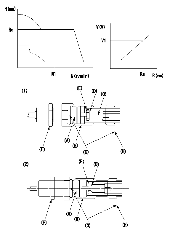
G:Red paint
H:Pump end face
P/N: part number of suitable shim
(1)Threaded type rack block
(2)Welded type rack block
Rack sensor adjustment
1. Threaded type rack sensor (-5*20, P type, no TICS rack limit).
(1)Screw in the bobbin (A) until it contacts the joint (B).
(2)Fix the pump lever.
(3)At speed N1 and rack position Ra, adjust the amount that the bobbin is screwed in so that the amp's output voltage is V1.
(4)Fix using the nut (F).
(5)Affix the caution plate to the upper part of the joint (B).
(6)Apply (G) at two places.
Connecting part between the joint (B) and the nut (F)
Connecting part between the end surface of the pump (H) and the joint (B)
2. Range for screw-in adjustment between the bobbin (A) and the joint (B) is 9 threads.
Screw in to the end from (the position where the bobbin (A) is rotated 9 turns).
Speed N1, rack position Ra, output voltage V1, rack sensor supply voltage 5+-0.01 (V)
----------
Ra=R1(13.9)mm N1=1350r/min V1=3+-0.01V
----------
----------
Ra=R1(13.9)mm N1=1350r/min V1=3+-0.01V
----------
0000001601 LEVER
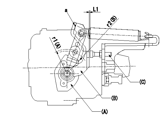
(a) Speed lever
(B) Accelerator lever
(C) Accelerator lever stopper bolt
1. Accelerator lever setting method
With the speed lever in the idling position, back off the accelerator lever stopper bolt L1 from where it contacts point a.
----------
r1=39mm r2=38mm L1=1+0.5mm
----------
----------
r1=39mm r2=38mm L1=1+0.5mm
----------
Timing setting

(1)Pump vertical direction
(2)Position of timer's threaded hole at No 1 cylinder's beginning of injection
(3)-
(4)-
----------
----------
a=(80deg)
----------
----------
a=(80deg)
Information:
For serial number specific information, please see SISWEB.
Features and Benefits
Cat Reman products offer excellent value to customers. Customers who want fast repair turn-around, superior quality and reliability, and lower repair costs will benefit from the use of these remanufactured products. Cat Reman parts provide immediate, off-the-shelf availability at a fraction of the new price.
Features Benefits
All critical engineering changes and updates included
Improved reliability and performance
Worldwide availability through Cat® parts distribution system
Customer access regardless of location
Backed by Caterpillar parts warranty
Consistent support
Core Acceptance
Core Acceptance Criteria for Cat Reman parts is simple, visual, and requires no special tools. Please consult the applicable Core Acceptance Criteria for each product for complete details. Core Acceptance Criteria can be found at catreman.cat.com/cac.
Unit Injectors Electronic - SELD0226-01
Warranty
Please consult the appropriate Caterpillar parts warranty statement for your area.
Core Management
Please refer to the Cat Core Management Information System (CMIS 2) Parts Information application describing all Cat Reman part/CAF and related information. Also refer to other CMIS 2 inquiry applications such as Customer Profiles, Inspection Reason Codes, Inspection Line Inquiry, Add Charge Information, Entitlement Activity, Entitlement Inquiry, CCR Inquiry, CCR Entry, Shipment Processing; Process Packaging Grief; and Reporting to properly manage core returns and monitor inspection performance. This information will be available to all dealers worldwide after your CMIS 2 conversion date. In the meantime, please continue to use the current CMIS Entitlement Parts Inquiry Screen describing the list of parts in a Core Acceptability Family (CAF) and related part number detail.
For the latest updates of Reman Policies and Core Management (SELD0122), Core Management Systems & Operations Procedures (SELD0040), and Shipping Instructions (SELD0039), go to the Reman Dealer website https://catreman.cat.com. If you have any questions regarding core return processing, feel free to call Corinth toll free at (800) 537-2928. Outside the US please refer to the Core section of the Reman website for appropriate contact information for your region.
For assistance with technical questions, call the Peoria Reman Technical Help Line also toll free at (888) 88-REMAN (outside the US call non-toll free +1-309-494-4342), or use our E-mail address, Reman_Help.
Contact Information:
Global Dealer Solutions Network
Parts Technical Support Team
Toll Free - North America: 1-877-228-2420
International: +1-309-266-4421
Electronic Requests: Send via Microsoft Customer Relationship Management (MSCRM)
For access and tutorial information: https://gdsn.cat.com/mscrm