Information injection-pump assembly
ZEXEL
101608-9550
1016089550
NISSAN-DIESEL
16713Z6808
16713z6808

Rating:
Cross reference number
ZEXEL
101608-9550
1016089550
NISSAN-DIESEL
16713Z6808
16713z6808
Zexel num
Bosch num
Firm num
Name
Calibration Data:
Adjustment conditions
Test oil
1404 Test oil ISO4113 or {SAEJ967d}
1404 Test oil ISO4113 or {SAEJ967d}
Test oil temperature
degC
40
40
45
Nozzle and nozzle holder
105780-8260
Bosch type code
9 430 610 133
Nozzle
105780-0120
Bosch type code
1 688 901 990
Nozzle holder
105780-2190
Opening pressure
MPa
18
Opening pressure
kgf/cm2
184
Injection pipe
Outer diameter - inner diameter - length (mm) mm 6-2-600
Outer diameter - inner diameter - length (mm) mm 6-2-600
Overflow valve
131425-0420
Overflow valve opening pressure
kPa
157
123
191
Overflow valve opening pressure
kgf/cm2
1.6
1.25
1.95
Tester oil delivery pressure
kPa
255
255
255
Tester oil delivery pressure
kgf/cm2
2.6
2.6
2.6
Direction of rotation (viewed from drive side)
Right R
Right R
Injection timing adjustment
Direction of rotation (viewed from drive side)
Right R
Right R
Injection order
1-4-2-6-
3-5
Pre-stroke
mm
3.7
3.65
3.75
Beginning of injection position
Drive side NO.1
Drive side NO.1
Difference between angles 1
Cal 1-4 deg. 60 59.5 60.5
Cal 1-4 deg. 60 59.5 60.5
Difference between angles 2
Cyl.1-2 deg. 120 119.5 120.5
Cyl.1-2 deg. 120 119.5 120.5
Difference between angles 3
Cal 1-6 deg. 180 179.5 180.5
Cal 1-6 deg. 180 179.5 180.5
Difference between angles 4
Cal 1-3 deg. 240 239.5 240.5
Cal 1-3 deg. 240 239.5 240.5
Difference between angles 5
Cal 1-5 deg. 300 299.5 300.5
Cal 1-5 deg. 300 299.5 300.5
Injection quantity adjustment
Adjusting point
-
Rack position
11.6
Pump speed
r/min
800
800
800
Average injection quantity
mm3/st.
90
88.4
91.6
Max. variation between cylinders
%
0
-3.5
3.5
Basic
*
Fixing the rack
*
Standard for adjustment of the maximum variation between cylinders
*
Injection quantity adjustment_02
Adjusting point
Z
Rack position
9.5+-0.5
Pump speed
r/min
265
265
265
Average injection quantity
mm3/st.
9
7.2
10.8
Max. variation between cylinders
%
0
-10
10
Fixing the rack
*
Standard for adjustment of the maximum variation between cylinders
*
Injection quantity adjustment_03
Adjusting point
A
Rack position
R1(11.6)
Pump speed
r/min
800
800
800
Average injection quantity
mm3/st.
90
89
91
Basic
*
Fixing the lever
*
Injection quantity adjustment_04
Adjusting point
B
Rack position
R1+0.9
Pump speed
r/min
1500
1500
1500
Average injection quantity
mm3/st.
95
91
99
Fixing the lever
*
Injection quantity adjustment_05
Adjusting point
C
Rack position
(R1-0.25
)
Pump speed
r/min
600
600
600
Average injection quantity
mm3/st.
86.5
82.5
90.5
Fixing the lever
*
Injection quantity adjustment_06
Adjusting point
I
Rack position
-
Pump speed
r/min
100
100
100
Average injection quantity
mm3/st.
120
120
130
Fixing the lever
*
Rack limit
*
Timer adjustment
Pump speed
r/min
(900)
Advance angle
deg.
0
0
0
Remarks
Start
Start
Timer adjustment_02
Pump speed
r/min
1080
Advance angle
deg.
2
1.5
2.5
Timer adjustment_03
Pump speed
r/min
1225
Advance angle
deg.
2
1.5
2.5
Timer adjustment_04
Pump speed
r/min
1425
Advance angle
deg.
6
5.5
6.5
Remarks
Finish
Finish
Test data Ex:
Governor adjustment
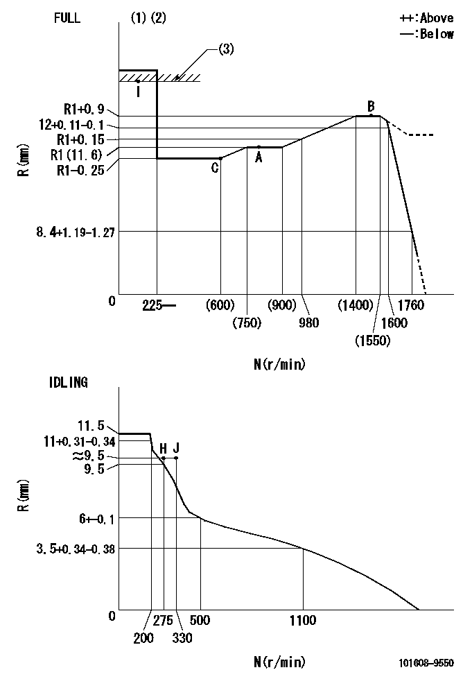
N:Pump speed
R:Rack position (mm)
(1)Torque cam stamping: T1
(2)Tolerance for racks not indicated: +-0.05mm.
(3)RACK LIMIT
----------
T1=M44
----------
----------
T1=M44
----------
Speed control lever angle

F:Full speed
I:Idle
(1)Use the hole at R = aa
(2)Stopper bolt set position 'H'
----------
aa=39mm
----------
a=20deg+-5deg b=42deg+-3deg
----------
aa=39mm
----------
a=20deg+-5deg b=42deg+-3deg
Stop lever angle
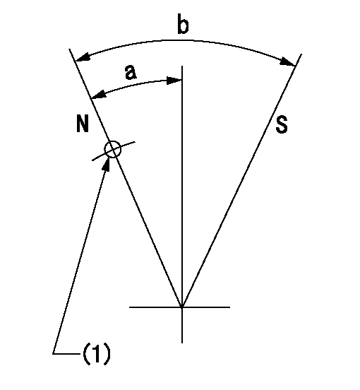
N:Pump normal
S:Stop the pump.
(1)Use the pin at R = aa
----------
aa=42mm
----------
a=25deg+-5deg b=40deg+-5deg
----------
aa=42mm
----------
a=25deg+-5deg b=40deg+-5deg
0000001501 LEVER
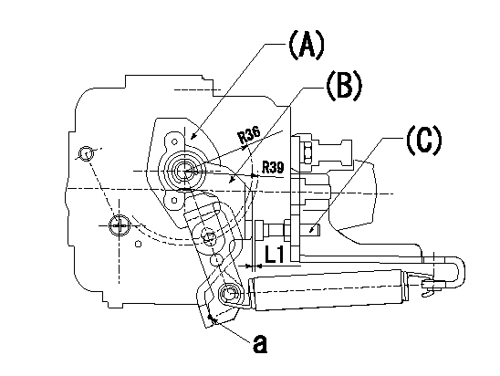
(a) Speed lever
(B) Accelerator lever
(C) Accelerator lever stopper bolt
1. Accelerator lever setting method
With the speed lever in the idling position, back off the accelerator lever stopper bolt L1 from where it contacts point a. (Back off 1+0.5 turns and set.)
----------
L1=1+0.5mm
----------
----------
L1=1+0.5mm
----------
Timing setting

(1)Pump vertical direction
(2)Position of timer's threaded hole at No 1 cylinder's beginning of injection
(3)-
(4)-
----------
----------
a=(60deg)
----------
----------
a=(60deg)
Information:
Flywheel
Installation of Flywheel Housing
Installation of flywheel housing(1) Install the oil seal to the flywheel housing.(2) Coat the contact surfaces of the crankcase and flywheel with ThreeBond 1104.(3) Align the holes in the flywheel housing and gasket with the dowel pins on the crankcase, and install them to the crankcase.Installation of Flywheel
(1) Install the flywheel to the crankshaft by aligning the hole with the dowel pin on the back-end of the crankshaft.(2) Place the washer and tighten the four bolts to the specified torque.
Installation of flywheelMeasurement of Flywheel Runout
Measure the flywheel runout with the flywheel installed to the crankshaft. If the standard value is exceeded, check the bolts for tightening condition and the mounting face for adhesion of foreign particles.
Measurement of face runout and circular runoutCylinder Head and Valve Mechanisms
Installation of Valve Stem Seal
(1) Apply engine oil to the valve stem, and insert it into the valve guide.(2) Place a new stem seal on the valve guide.(3) Using the stem seal installer, install the stem seal to the valve guide, making use of the valve stem as a guide.
Installation of valve stem sealInstallation of Valves and Valve Springs
(1) Place the valve spring and retainer on the valve guide, and install the valve cotter using the valve spring pusher.
Excessive compression of the valve spring can cause the retainer to contact the stem seal and damage the seal.
Installation of valve and valve spring(2) Using a soft-faced hammer, tap the top of the valve stem several times to make sure that the spring and valve cotter are securely installed.
Confirmation of secure valve cotter installationInstallation of Cylinder Head Gasket
(1) Make sure that the top face of the crankcase and piston upper surfaces are clean and free of dust.(2) Place a new gasket of the crankcase, making sure that the dowel pins on the top face of the crankcase enter the holes in the gasket.
Do not use a liquid gasket.
Installation of cylinder head gasketInstallation of Cylinder Head
Place the cylinder head on the head gasket, making sure that the dowel pins on the top face of the crankcase enters the holes in the cylinder head.
Installation of cylinder head assemblyTightening of Cylinder Head Bolts
Tighten the cylinder head bolts, following the tightening sequence shown in the diagram two or three times before reaching the specified torque.
Cylinder head bolt tightening sequenceAssembly of Rocker Arm and Rocker Shaft Assembly
When installing the rocker arms, make sure that the shaft assembly marks face the front of the engine, as shown in the diagram. After the assembly, make sure that the rocker arms move smoothly.
Assembly of rocker shaft assemblyInstallation of Pushrods
(1) Insert the pushrods in the cylinder head through the pushrod holes.(2) Make sure that the ball end of each pushrod rests securely on the curved surface of the tappet.Installation of Rocker Shaft Assemblies
(1) Install the valve caps.(2) When installing the rocker shaft brackets, tighten the long bolts first, then tighten the short bolts (reversal of removal sequence).
Installation of rocker shaft assemblyAdjustment of Valve Clearances
(1) Confirming the top dead center on the