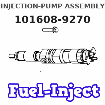
Information injection-pump assembly
ZEXEL
101608-9270
1016089270
NISSAN-DIESEL
16713Z6702
16713z6702
Rating:
Cross reference number
ZEXEL
101608-9270
1016089270
NISSAN-DIESEL
16713Z6702
16713z6702
Zexel num
Bosch num
Firm num
Name
Calibration Data:
Adjustment conditions
Test oil
1404 Test oil ISO4113 or {SAEJ967d}
1404 Test oil ISO4113 or {SAEJ967d}
Test oil temperature
degC
40
40
45
Nozzle and nozzle holder
105780-8140
Bosch type code
EF8511/9A
Nozzle
105780-0000
Bosch type code
DN12SD12T
Nozzle holder
105780-2080
Bosch type code
EF8511/9
Opening pressure
MPa
17.2
Opening pressure
kgf/cm2
175
Injection pipe
Outer diameter - inner diameter - length (mm) mm 6-2-600
Outer diameter - inner diameter - length (mm) mm 6-2-600
Overflow valve
134424-1520
Overflow valve opening pressure
kPa
162
147
177
Overflow valve opening pressure
kgf/cm2
1.65
1.5
1.8
Tester oil delivery pressure
kPa
157
157
157
Tester oil delivery pressure
kgf/cm2
1.6
1.6
1.6
Direction of rotation (viewed from drive side)
Right R
Right R
Injection timing adjustment
Direction of rotation (viewed from drive side)
Right R
Right R
Injection order
1-4-2-6-
3-5
Pre-stroke
mm
3.4
3.35
3.45
Beginning of injection position
Drive side NO.1
Drive side NO.1
Difference between angles 1
Cal 1-4 deg. 60 59.5 60.5
Cal 1-4 deg. 60 59.5 60.5
Difference between angles 2
Cyl.1-2 deg. 120 119.5 120.5
Cyl.1-2 deg. 120 119.5 120.5
Difference between angles 3
Cal 1-6 deg. 180 179.5 180.5
Cal 1-6 deg. 180 179.5 180.5
Difference between angles 4
Cal 1-3 deg. 240 239.5 240.5
Cal 1-3 deg. 240 239.5 240.5
Difference between angles 5
Cal 1-5 deg. 300 299.5 300.5
Cal 1-5 deg. 300 299.5 300.5
Injection quantity adjustment
Adjusting point
-
Rack position
11.8
Pump speed
r/min
800
800
800
Average injection quantity
mm3/st.
70.5
68.9
72.1
Max. variation between cylinders
%
0
-3.5
3.5
Basic
*
Fixing the rack
*
Standard for adjustment of the maximum variation between cylinders
*
Injection quantity adjustment_02
Adjusting point
H
Rack position
9.5+-0.5
Pump speed
r/min
275
275
275
Average injection quantity
mm3/st.
10
8.2
11.8
Max. variation between cylinders
%
0
-10
10
Fixing the rack
*
Standard for adjustment of the maximum variation between cylinders
*
Injection quantity adjustment_03
Adjusting point
A
Rack position
R1(11.8)
Pump speed
r/min
800
800
800
Average injection quantity
mm3/st.
70.5
69.5
71.5
Basic
*
Fixing the lever
*
Injection quantity adjustment_04
Adjusting point
B
Rack position
R1-0.15
Pump speed
r/min
1500
1500
1500
Average injection quantity
mm3/st.
77
73
81
Fixing the lever
*
Injection quantity adjustment_05
Adjusting point
I
Rack position
-
Pump speed
r/min
100
100
100
Average injection quantity
mm3/st.
80
80
90
Fixing the lever
*
Rack limit
*
Timer adjustment
Pump speed
r/min
1200--
Advance angle
deg.
0
0
0
Remarks
Start
Start
Timer adjustment_02
Pump speed
r/min
1150
Advance angle
deg.
0.5
Timer adjustment_03
Pump speed
r/min
1500
Advance angle
deg.
6.5
6.2
6.8
Remarks
Finish
Finish
Test data Ex:
Governor adjustment
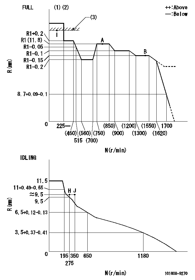
N:Pump speed
R:Rack position (mm)
(1)Torque cam stamping: T1
(2)Tolerance for racks not indicated: +-0.05mm.
(3)RACK LIMIT
----------
T1=M84
----------
----------
T1=M84
----------
Speed control lever angle

F:Full speed
I:Idle
(1)Use the hole at R = aa
(2)Stopper bolt set position 'H'
----------
aa=100mm
----------
a=26.5deg+-5deg b=46deg+-3deg
----------
aa=100mm
----------
a=26.5deg+-5deg b=46deg+-3deg
Stop lever angle
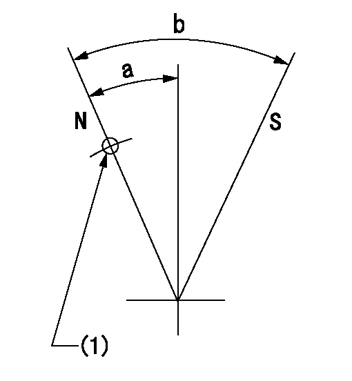
N:Pump normal
S:Stop the pump.
(1)Use the pin at R = aa
----------
aa=42mm
----------
a=25deg+-5deg b=40deg+-5deg
----------
aa=42mm
----------
a=25deg+-5deg b=40deg+-5deg
0000001501 RACK SENSOR
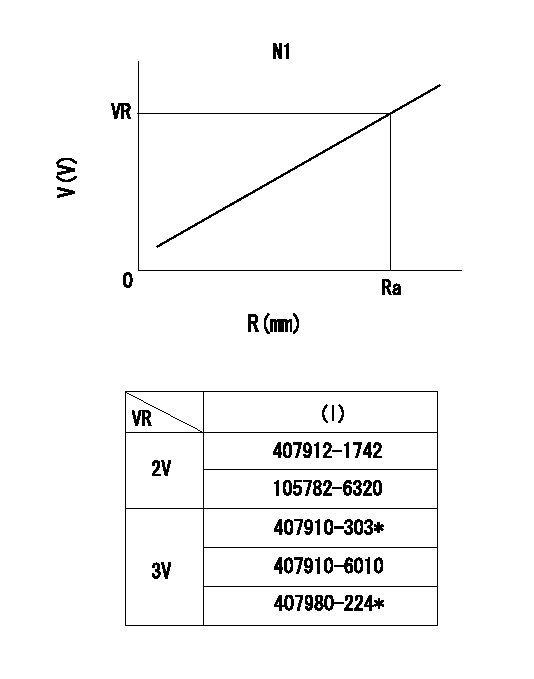
R:Rack position (mm)
V:Voltage (V)
After installing the rack sensor, confirm the output value (VR).
----------
N1=800r/min Ra=R1(11.8)mm VR=2.5+-0.01V
----------
----------
N1=800r/min Ra=R1(11.8)mm VR=2.5+-0.01V
----------
Timing setting

(1)Pump vertical direction
(2)Position of timer's threaded hole at No 1 cylinder's beginning of injection
(3)-
(4)-
----------
----------
a=(60deg)
----------
----------
a=(60deg)
Information:
Starting System
Use a D.C. voltmeter to locate starting system components which do not function.Move starting control switch to energize the starter solenoid. Starter solenoid operation is audible as the starter motor pinion engages with the ring gear on the engine flywheel. The solenoid operation should also close the electric circuit to the motor. Attach one voltmeter lead to the solenoid terminal that is connected to the motor. Ground the other lead. Energize the starter solenoid and observe the voltmeter. A battery voltage reading indicates the malfunction is in the motor. It must be removed for further testing. No voltmeter reading indicates that the solenoid contacts do not close and the solenoid must be repaired or the starter pinion clearance should be adjusted.A starting motor solenoid that will not operate may not be receiving battery current. Attach one lead of the voltmeter to the solenoid battery cable connection. Ground the other lead. No voltmeter reading indicates a faulty circuit from the battery. A voltmeter reading indicates further testing is necessary.Continue the test by attaching one voltmeter lead to the starting motor solenoid small wire terminal and the other lead to ground. Observe the voltmeter and energize the starter solenoid. A voltmeter reading indicates that the malfunction is in the solenoid. No voltmeter reading indicates the starter switch or wiring is the fault.Attach one lead of the voltmeter to the starter switch battery wire terminal and ground the other lead. A voltmeter reading indicates a defective switch.A starting motor that operates too slow can be overloaded by excessive mechanical friction within the engine being started. Slow starting motor operation can also be caused by shorts, loose connections and/or excessive dirt within the motor.Pinion Clearance Adjustment (Prestolite)
There are two adjustments on this type motor. Armature end play and pinion position.Armature End Play
Adjust the end play to .005 to .030 in. (0.13 to 0.76 mm) by adding or removing thrust washers on the commutator end of the armature shaft.Pinion Position
This adjustment is accomplished in two steps.1. To adjust the pinion distance, connect the solenoid to a 12 volt battery as shown.Momentarily flash the jumper lead from the motor terminal stud of the solenoid to the terminal stud at (1) in the commutator end head to shift the solenoid and drive into the cranking position.
CONNECTIONS FOR ADJUSTING THE PINION POSITION
1. Jumper lead flashing point.Remove the jumper lead. The drive will remain in the cranking position until the battery is disconnected.Push the drive toward the commutator end of the motor to eliminate any slack movement in the linkage and measure the distance between the outside edge of the drive sleeve and the thrust washer. The distance (3) must be .02 to .05 in. (0.5 to 1.3 mm).Adjust to this dimension by turning the adjusting nut (2) in or out as required.
PINION POSITION ADJUSTMENT
2. Adjusting nut. 3. Distance.2. To test assembly of solenoid, it will be necessary to have an interference block cut to the dimensions shown.
INTERFERENCE BLOCK DIMENSIONSConnect the solenoid to 24 volts as