Information injection-pump assembly
ZEXEL
101608-9260
1016089260
NISSAN-DIESEL
16713Z6701
16713z6701

Rating:
Cross reference number
ZEXEL
101608-9260
1016089260
NISSAN-DIESEL
16713Z6701
16713z6701
Zexel num
Bosch num
Firm num
Name
Calibration Data:
Adjustment conditions
Test oil
1404 Test oil ISO4113 or {SAEJ967d}
1404 Test oil ISO4113 or {SAEJ967d}
Test oil temperature
degC
40
40
45
Nozzle and nozzle holder
105780-8140
Bosch type code
EF8511/9A
Nozzle
105780-0000
Bosch type code
DN12SD12T
Nozzle holder
105780-2080
Bosch type code
EF8511/9
Opening pressure
MPa
17.2
Opening pressure
kgf/cm2
175
Injection pipe
Outer diameter - inner diameter - length (mm) mm 6-2-600
Outer diameter - inner diameter - length (mm) mm 6-2-600
Overflow valve
134424-1520
Overflow valve opening pressure
kPa
162
147
177
Overflow valve opening pressure
kgf/cm2
1.65
1.5
1.8
Tester oil delivery pressure
kPa
157
157
157
Tester oil delivery pressure
kgf/cm2
1.6
1.6
1.6
Direction of rotation (viewed from drive side)
Right R
Right R
Injection timing adjustment
Direction of rotation (viewed from drive side)
Right R
Right R
Injection order
1-4-2-6-
3-5
Pre-stroke
mm
3.4
3.35
3.45
Beginning of injection position
Drive side NO.1
Drive side NO.1
Difference between angles 1
Cal 1-4 deg. 60 59.5 60.5
Cal 1-4 deg. 60 59.5 60.5
Difference between angles 2
Cyl.1-2 deg. 120 119.5 120.5
Cyl.1-2 deg. 120 119.5 120.5
Difference between angles 3
Cal 1-6 deg. 180 179.5 180.5
Cal 1-6 deg. 180 179.5 180.5
Difference between angles 4
Cal 1-3 deg. 240 239.5 240.5
Cal 1-3 deg. 240 239.5 240.5
Difference between angles 5
Cal 1-5 deg. 300 299.5 300.5
Cal 1-5 deg. 300 299.5 300.5
Injection quantity adjustment
Adjusting point
-
Rack position
11.8
Pump speed
r/min
800
800
800
Average injection quantity
mm3/st.
70.5
68.9
72.1
Max. variation between cylinders
%
0
-3.5
3.5
Basic
*
Fixing the rack
*
Standard for adjustment of the maximum variation between cylinders
*
Injection quantity adjustment_02
Adjusting point
H
Rack position
9.5+-0.5
Pump speed
r/min
275
275
275
Average injection quantity
mm3/st.
10
8.2
11.8
Max. variation between cylinders
%
0
-10
10
Fixing the rack
*
Standard for adjustment of the maximum variation between cylinders
*
Injection quantity adjustment_03
Adjusting point
A
Rack position
R1(11.8)
Pump speed
r/min
800
800
800
Average injection quantity
mm3/st.
70.5
69.5
71.5
Basic
*
Fixing the lever
*
Injection quantity adjustment_04
Adjusting point
B
Rack position
R1-0.15
Pump speed
r/min
1500
1500
1500
Average injection quantity
mm3/st.
77
73
81
Fixing the lever
*
Injection quantity adjustment_05
Adjusting point
I
Rack position
-
Pump speed
r/min
100
100
100
Average injection quantity
mm3/st.
80
80
90
Fixing the lever
*
Rack limit
*
Timer adjustment
Pump speed
r/min
1200--
Advance angle
deg.
0
0
0
Remarks
Start
Start
Timer adjustment_02
Pump speed
r/min
1150
Advance angle
deg.
0.5
Timer adjustment_03
Pump speed
r/min
1500
Advance angle
deg.
6.5
6.2
6.8
Remarks
Finish
Finish
Test data Ex:
Governor adjustment
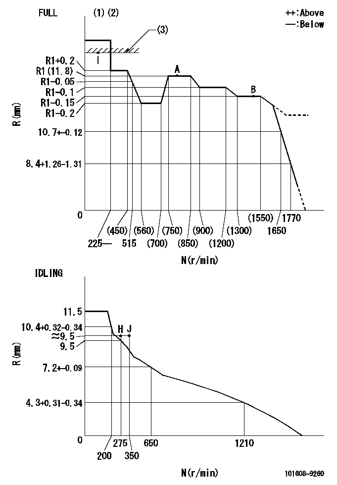
N:Pump speed
R:Rack position (mm)
(1)Torque cam stamping: T1
(2)Tolerance for racks not indicated: +-0.05mm.
(3)RACK LIMIT
----------
T1=M35
----------
----------
T1=M35
----------
Speed control lever angle

F:Full speed
I:Idle
(1)Use the hole at R = aa
(2)Stopper bolt set position 'H'
----------
aa=36mm
----------
a=25deg+-5deg b=37deg+-3deg
----------
aa=36mm
----------
a=25deg+-5deg b=37deg+-3deg
Stop lever angle
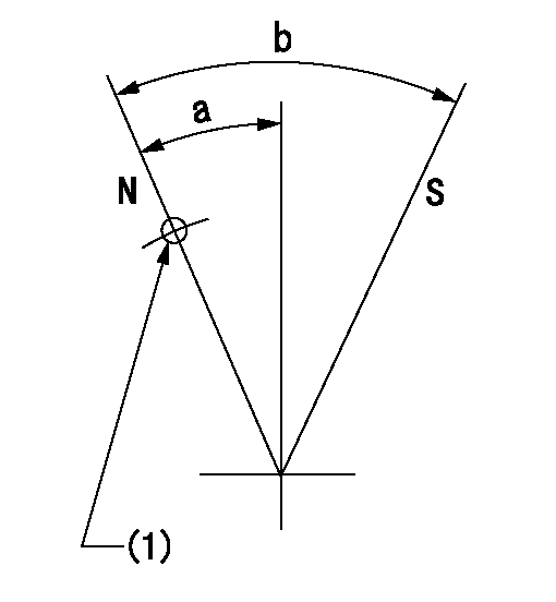
N:Pump normal
S:Stop the pump.
(1)Use the pin at R = aa
----------
aa=42mm
----------
a=25deg+-5deg b=40deg+-5deg
----------
aa=42mm
----------
a=25deg+-5deg b=40deg+-5deg
0000001501 RACK SENSOR
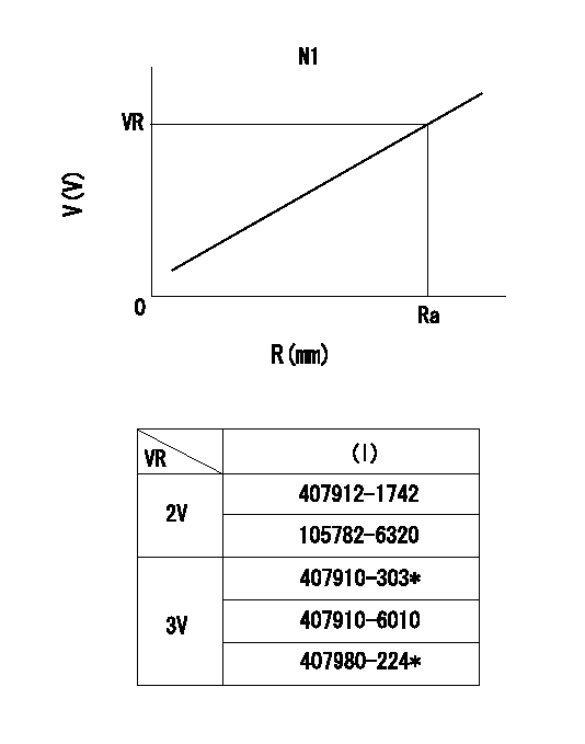
R:Rack position (mm)
V:Voltage (V)
After installing the rack sensor, confirm the output value (VR).
----------
N1=800r/min Ra=R1(11.8)mm VR=2.5+-0.01V
----------
----------
N1=800r/min Ra=R1(11.8)mm VR=2.5+-0.01V
----------
Timing setting

(1)Pump vertical direction
(2)Position of timer's threaded hole at No 1 cylinder's beginning of injection
(3)-
(4)-
----------
----------
a=(60deg)
----------
----------
a=(60deg)
Information:
Cooling System
The centrifugal-type water pump mounts on the front cover and is belt driven by the crankshaft pulley. The pump has two outlets. Coolant from the outlet on the right side of the pump flows through a passage in the front cover to the left bank of the engine, and coolant from the outlet on the left flows to the right bank.The coolant circulates through the block to the cylinder head. Coolant flows from the heads through connecting sleeves to the return manifold in the front cover. Orifices in the sleeves control the flow from the heads.Part of the coolant to the left bank is diverted from the block to the oil cooler. External lines direct coolant from the block to the cooler and back to the return manifold in the front cover.An internal passage in the front cover directs the coolant from the return manifold to the water pump inlet. If the thermostats are closed the coolant flows to the pump and is recirculated through the engine. If they are open, coolant flows from the return manifold to the radiator and from there to the pump.The radiator is constructed with a top tank above the core and an expansion tank either above or separate from the top tank. A vent tube connects the radiator top tank and the expansion tank. The expansion tank has a shunt line which connects to the water pump inlet. This shunt system maintains a positive, static head of coolant at the pump inlet to prevent cavitation under all operating conditions. When filling the cooling system, coolant from the expansion tank flows through the shunt line to the water pump inlet and fills the engine block from the bottom. By filling the system from the bottom, air in the system is forced out through the top tank, through the vent tube into the expansion tank.The two thermostats are located at the inlet to the water pump. The inlet-regulated cooling system maintains positive coolant temperature control with decreased engine warm up time.When the thermostats are closed, coolant is circulated through the block and heads and back to the water pump by way of an internal passage in the front cover. When the thermostats are open, the bypass flow is restricted and the engine coolant flows through the radiator and returns through the inlet elbow to the water pump. Without the thermostats installed, the coolant will continually bypass the radiator, and overheating will result.Electrical System
The electrical system is a combination of three separate electric circuits: the charging circuit, the starting circuit and the lighting or load circuit. Each circuit is dependent on some of the same components. The battery (batteries), disconnect switch, circuit breaker, ammeter, cables and wires from the battery are common in each of the circuits.The charging circuit is in operation when the engine is operating. The electricity producing (charging) unit is an alternator. A regulator in the circuit senses the state of charge in the battery and regulates the electrical output to