Information injection-pump assembly
ZEXEL
101608-9240
1016089240
NISSAN-DIESEL
16713Z6666
16713z6666
Rating:
Cross reference number
ZEXEL
101608-9240
1016089240
NISSAN-DIESEL
16713Z6666
16713z6666
Zexel num
Bosch num
Firm num
Name
Calibration Data:
Adjustment conditions
Test oil
1404 Test oil ISO4113 or {SAEJ967d}
1404 Test oil ISO4113 or {SAEJ967d}
Test oil temperature
degC
40
40
45
Nozzle and nozzle holder
105780-8260
Bosch type code
9 430 610 133
Nozzle
105780-0120
Bosch type code
1 688 901 990
Nozzle holder
105780-2190
Opening pressure
MPa
18
Opening pressure
kgf/cm2
184
Injection pipe
Outer diameter - inner diameter - length (mm) mm 6-2-600
Outer diameter - inner diameter - length (mm) mm 6-2-600
Overflow valve
131424-8921
Overflow valve opening pressure
kPa
157
123
191
Overflow valve opening pressure
kgf/cm2
1.6
1.25
1.95
Tester oil delivery pressure
kPa
255
255
255
Tester oil delivery pressure
kgf/cm2
2.6
2.6
2.6
Direction of rotation (viewed from drive side)
Left L
Left L
Injection timing adjustment
Direction of rotation (viewed from drive side)
Left L
Left L
Injection order
1-4-2-6-
3-5
Pre-stroke
mm
3.7
3.65
3.75
Beginning of injection position
Governor side NO.1
Governor side NO.1
Difference between angles 1
Cal 1-4 deg. 60 59.5 60.5
Cal 1-4 deg. 60 59.5 60.5
Difference between angles 2
Cyl.1-2 deg. 120 119.5 120.5
Cyl.1-2 deg. 120 119.5 120.5
Difference between angles 3
Cal 1-6 deg. 180 179.5 180.5
Cal 1-6 deg. 180 179.5 180.5
Difference between angles 4
Cal 1-3 deg. 240 239.5 240.5
Cal 1-3 deg. 240 239.5 240.5
Difference between angles 5
Cal 1-5 deg. 300 299.5 300.5
Cal 1-5 deg. 300 299.5 300.5
Injection quantity adjustment
Adjusting point
-
Rack position
11.8
Pump speed
r/min
800
800
800
Average injection quantity
mm3/st.
95
93.4
96.6
Max. variation between cylinders
%
0
-3.5
3.5
Basic
*
Fixing the rack
*
Standard for adjustment of the maximum variation between cylinders
*
Injection quantity adjustment_02
Adjusting point
Z
Rack position
9.5+-0.5
Pump speed
r/min
280
280
280
Average injection quantity
mm3/st.
12
11
13
Max. variation between cylinders
%
0
-10
10
Fixing the rack
*
Standard for adjustment of the maximum variation between cylinders
*
Injection quantity adjustment_03
Adjusting point
A
Rack position
R1(11.8)
Pump speed
r/min
800
800
800
Average injection quantity
mm3/st.
95
94
96
Basic
*
Fixing the lever
*
Injection quantity adjustment_04
Adjusting point
B
Rack position
R1+0.9
Pump speed
r/min
1450
1450
1450
Average injection quantity
mm3/st.
100.5
96.5
104.5
Fixing the lever
*
Injection quantity adjustment_05
Adjusting point
I
Rack position
-
Pump speed
r/min
100
100
100
Average injection quantity
mm3/st.
125
125
135
Fixing the lever
*
Rack limit
*
Timer adjustment
Pump speed
r/min
970--
Advance angle
deg.
0
0
0
Remarks
Start
Start
Timer adjustment_02
Pump speed
r/min
920
Advance angle
deg.
0.5
Timer adjustment_03
Pump speed
r/min
(1000)
Advance angle
deg.
1.5
1
2
Timer adjustment_04
Pump speed
r/min
1160
Advance angle
deg.
1.5
1
2
Timer adjustment_05
Pump speed
r/min
1450
Advance angle
deg.
7
6.5
7.5
Remarks
Finish
Finish
Test data Ex:
Governor adjustment
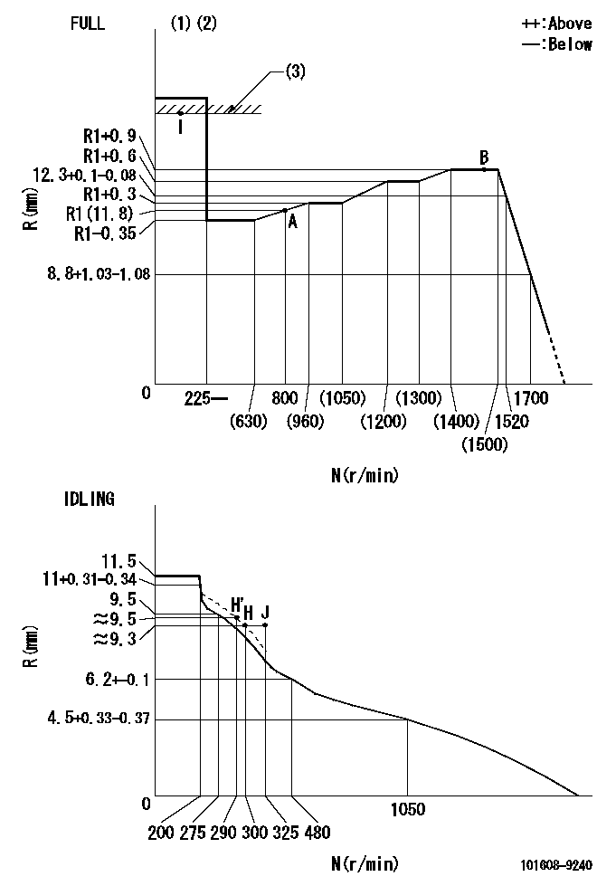
N:Pump speed
R:Rack position (mm)
(1)Torque cam stamping: T1
(2)Tolerance for racks not indicated: +-0.05mm.
(3)RACK LIMIT
----------
T1=L85
----------
----------
T1=L85
----------
Speed control lever angle

F:Full speed
I:Idle
(1)Use the hole at R = aa
(2)Stopper bolt set position 'H'
----------
aa=39mm
----------
a=6.5deg+-5deg b=35deg+-3deg
----------
aa=39mm
----------
a=6.5deg+-5deg b=35deg+-3deg
Stop lever angle
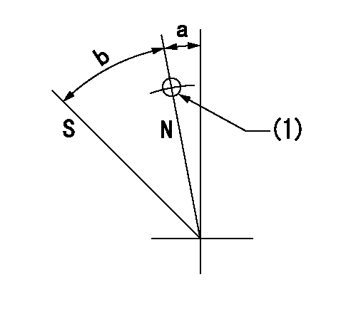
N:Pump normal
S:Stop the pump.
(1)Use the pin at R = aa
----------
aa=42mm
----------
a=5deg+-5deg b=40deg+-5deg
----------
aa=42mm
----------
a=5deg+-5deg b=40deg+-5deg
0000001501 LEVER
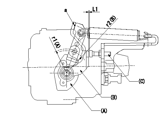
(a) Speed lever
(B) Accelerator lever
(C) Accelerator lever stopper bolt
1. Accelerator lever setting method
With the speed lever in the idling position, back off the accelerator lever stopper bolt L1 from where it contacts point a.
----------
r1=39mm r2=38mm L1=1+0.5mm
----------
----------
r1=39mm r2=38mm L1=1+0.5mm
----------
Timing setting

(1)Pump vertical direction
(2)Position of timer's threaded hole at No 1 cylinder's beginning of injection
(3)-
(4)-
----------
----------
a=(80deg)
----------
----------
a=(80deg)
Information:
Checking Field Coil for Insulation(3) Inspecting the stator coil(a) Check for conduction between lead wires of the stator coil. If there is no conduction, the stator coil is suspected to be broken. Replace the stator coil.
Checking Stator Coil for Conduction(b) Check for conduction between each lead wire and stator core. If any conduction is found, the stator coil is suspected to be poor in insulation. Replace the stator coil.
Checking Stator Coil for InsulationAssembly of Alternator
Reassemble the alternator assembly in the reverse order of disassembly, giving care to the following:(1) The rear bearing has an eccentric groove. Install the snap ring so that its projection fits in with the deepest part of the groove.(2) When installing a new rear bearing, press-fit the bearing with its groove facing the slip ring side.(3) When press-fitting the rear bearing into the rear bracket, heat the bracket. CAUTION* Pass a wire through the small hole in the rear bracket to lift the brushes before installing the rotor to the rear bracket. Remove the wire after the rotor is installed.
Lifting BrushesInstallation
Install the alternator in the reverse order of removal.(1) Insertion of spacerWhen installing the support bolts, insert the spacer in place using the following procedure:(a) Push in the support bolts to the normal position. (Leave the nuts removed from the bolts.)(b) Push the alternator backward. Measure the clearance between the alternator rear bracket and gear case bracket to determine the number of spacers to be inserted into the clearance (0.2 mm maximum).(c) Reinstall the alternator with the necessary spacer inserted in place. Tighten the support bolt nuts securely.(d) Perform the belt tension adjustment.
Inserting SpacerDynamo, Regulator and Rectifier
Specifications
For specifications, see 7-01.Inspection
(1) Checking the unit in serviceMeasure battery voltage across terminals with a circuit tester. It is considered normal if no-load measurement is kept steady at about 15.0V at 5000rpm or more of alternator speed.
Measuring Voltage Across Battery Terminals(2) Checking the regulator aloneTo judge whether the regulator itself is acceptable or not, check the regulator for normal conduction by connecting the circuit tester to the lead wires as follows. For testing, use the circuit tester as an ohmmeter.
Lead Outlet CouplerInstallation
(1) Heat affects largely on the regulator and rectifier. Position them in a well-ventilated place. Install the regulator in proper direction so that the outlet of leads from the body faces downward.GLOW PLUG
Removal and Installation
Glow plug tightening torque: 1.5 - 2.0 kgmInspection
Check for conduction between the glow plug terminal and body. If the plug is not conductive at all or shows a large resistance, replace the plug.
Checking Glow PlugKEY-OFF STOP SYSTEM
General
The function of this system is to actuate the fuel cutoff solenoid when the starter key is placed in the OFF position. It also has the emergency engine stop function by actuating the control timer in case of abnormal lowering of oil pressure (and abnormal increase of coolant temperature for special-specification engines).Control Timer Unit
Timer UnitFuel Cutoff Solenoid (Push type)
(1) Specification
Fuel Cutoff Solenoid (Push type)(2) Solenoid installation procedure(a) Temporarily fit the solenoid (1) and nut (2) to the