Information injection-pump assembly
ZEXEL
101608-9230
1016089230
NISSAN-DIESEL
16713Z6665
16713z6665

Rating:
Cross reference number
ZEXEL
101608-9230
1016089230
NISSAN-DIESEL
16713Z6665
16713z6665
Zexel num
Bosch num
Firm num
Name
Calibration Data:
Adjustment conditions
Test oil
1404 Test oil ISO4113 or {SAEJ967d}
1404 Test oil ISO4113 or {SAEJ967d}
Test oil temperature
degC
40
40
45
Nozzle and nozzle holder
105780-8260
Bosch type code
9 430 610 133
Nozzle
105780-0120
Bosch type code
1 688 901 990
Nozzle holder
105780-2190
Opening pressure
MPa
18
Opening pressure
kgf/cm2
184
Injection pipe
Outer diameter - inner diameter - length (mm) mm 6-2-600
Outer diameter - inner diameter - length (mm) mm 6-2-600
Overflow valve
131424-8921
Overflow valve opening pressure
kPa
157
123
191
Overflow valve opening pressure
kgf/cm2
1.6
1.25
1.95
Tester oil delivery pressure
kPa
255
255
255
Tester oil delivery pressure
kgf/cm2
2.6
2.6
2.6
Direction of rotation (viewed from drive side)
Left L
Left L
Injection timing adjustment
Direction of rotation (viewed from drive side)
Left L
Left L
Injection order
1-4-2-6-
3-5
Pre-stroke
mm
3.7
3.65
3.75
Beginning of injection position
Governor side NO.1
Governor side NO.1
Difference between angles 1
Cal 1-4 deg. 60 59.5 60.5
Cal 1-4 deg. 60 59.5 60.5
Difference between angles 2
Cyl.1-2 deg. 120 119.5 120.5
Cyl.1-2 deg. 120 119.5 120.5
Difference between angles 3
Cal 1-6 deg. 180 179.5 180.5
Cal 1-6 deg. 180 179.5 180.5
Difference between angles 4
Cal 1-3 deg. 240 239.5 240.5
Cal 1-3 deg. 240 239.5 240.5
Difference between angles 5
Cal 1-5 deg. 300 299.5 300.5
Cal 1-5 deg. 300 299.5 300.5
Injection quantity adjustment
Adjusting point
-
Rack position
11.8
Pump speed
r/min
800
800
800
Average injection quantity
mm3/st.
95
93.4
96.6
Max. variation between cylinders
%
0
-3.5
3.5
Basic
*
Fixing the rack
*
Standard for adjustment of the maximum variation between cylinders
*
Injection quantity adjustment_02
Adjusting point
Z
Rack position
9.5+-0.5
Pump speed
r/min
280
280
280
Average injection quantity
mm3/st.
12
11
13
Max. variation between cylinders
%
0
-10
10
Fixing the rack
*
Standard for adjustment of the maximum variation between cylinders
*
Injection quantity adjustment_03
Adjusting point
A
Rack position
R1(11.8)
Pump speed
r/min
800
800
800
Average injection quantity
mm3/st.
95
94
96
Basic
*
Fixing the lever
*
Injection quantity adjustment_04
Adjusting point
B
Rack position
R1+0.9
Pump speed
r/min
1450
1450
1450
Average injection quantity
mm3/st.
100.5
96.5
104.5
Fixing the lever
*
Injection quantity adjustment_05
Adjusting point
I
Rack position
-
Pump speed
r/min
100
100
100
Average injection quantity
mm3/st.
125
125
135
Fixing the lever
*
Rack limit
*
Timer adjustment
Pump speed
r/min
970--
Advance angle
deg.
0
0
0
Remarks
Start
Start
Timer adjustment_02
Pump speed
r/min
920
Advance angle
deg.
0.5
Timer adjustment_03
Pump speed
r/min
(1000)
Advance angle
deg.
1.5
1
2
Timer adjustment_04
Pump speed
r/min
1160
Advance angle
deg.
1.5
1
2
Timer adjustment_05
Pump speed
r/min
1450
Advance angle
deg.
7
6.5
7.5
Remarks
Finish
Finish
Test data Ex:
Governor adjustment
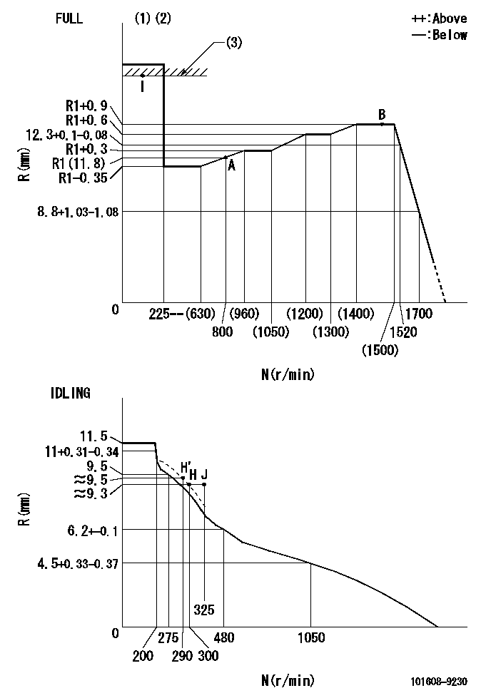
N:Pump speed
R:Rack position (mm)
(1)Torque cam stamping: T1
(2)Tolerance for racks not indicated: +-0.05mm.
(3)RACK LIMIT
----------
T1=L85
----------
----------
T1=L85
----------
Speed control lever angle

F:Full speed
I:Idle
(1)Use the hole at R = aa
(2)Stopper bolt set position 'H'
----------
aa=38mm
----------
a=6.5deg+-5deg b=35deg+-3deg
----------
aa=38mm
----------
a=6.5deg+-5deg b=35deg+-3deg
Stop lever angle
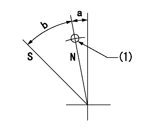
N:Pump normal
S:Stop the pump.
(1)Use the pin at R = aa
----------
aa=42mm
----------
a=5deg+-5deg b=40deg+-5deg
----------
aa=42mm
----------
a=5deg+-5deg b=40deg+-5deg
Timing setting

(1)Pump vertical direction
(2)Position of timer's threaded hole at No 1 cylinder's beginning of injection
(3)-
(4)-
----------
----------
a=(80deg)
----------
----------
a=(80deg)
Information:
GENERAL
Specifications
Construction
Cooling System Component Parts(1) Cooling fan(2) Water pump pulley(3) Water pump assembly(4) V-belt(5) Thermostat(6) Thermostat fitting(7) Thermoswitch(8) Bypass pipeFAN AND FAN BELT
Fan Belt Inspection
For fan belt tension, see 0-06 MAINTENANCE.
Inspecting Fan BeltFan Inspection
Check the fan for cracks, damaged and deformation. If any, replace the fan.
Inspecting FanWATER PUMP
Removal and Installation
(1) Remove the fan and fan belt.(2) Remove the water pump.(3) When installing the water pump, reverse the above-mentioned order of removal.
Removing Water PumpInspection
Check the water pump for water leak, rough rotation, and cracks. If any, replace the water pump assembly.THERMOSTAT
Removal and Installation
Pay attention to the following:(1) Never allow the flange to protrude from the faucet joint.(2) Renew the gasket.
Installing ThermostatInspection
If the thermostat does not operate properly, replace it.
Inspecting Thermostat WATER TEMPERATURE GAUGE UNIT AND THERMOSWITCH
Inspection of Water Temperature Gauge Unit
If the gauge does not function properly, replace it.
Inspecting Temperature Gauge Unit CAUTION Handle hot oil with special care not to cause a scald or a fire.Inspection of Thermoswitch
Inspecting Thermoswitch CAUTION Handle hot oil with special care not to cause a scald or a fire.