Information injection-pump assembly
ZEXEL
101608-9220
1016089220
NISSAN-DIESEL
16713Z6664
16713z6664
Rating:
Cross reference number
ZEXEL
101608-9220
1016089220
NISSAN-DIESEL
16713Z6664
16713z6664
Zexel num
Bosch num
Firm num
Name
Calibration Data:
Adjustment conditions
Test oil
1404 Test oil ISO4113 or {SAEJ967d}
1404 Test oil ISO4113 or {SAEJ967d}
Test oil temperature
degC
40
40
45
Nozzle and nozzle holder
105780-8260
Bosch type code
9 430 610 133
Nozzle
105780-0120
Bosch type code
1 688 901 990
Nozzle holder
105780-2190
Opening pressure
MPa
18
Opening pressure
kgf/cm2
184
Injection pipe
Outer diameter - inner diameter - length (mm) mm 6-2-600
Outer diameter - inner diameter - length (mm) mm 6-2-600
Overflow valve
131425-0420
Overflow valve opening pressure
kPa
157
123
191
Overflow valve opening pressure
kgf/cm2
1.6
1.25
1.95
Tester oil delivery pressure
kPa
255
255
255
Tester oil delivery pressure
kgf/cm2
2.6
2.6
2.6
Direction of rotation (viewed from drive side)
Right R
Right R
Injection timing adjustment
Direction of rotation (viewed from drive side)
Right R
Right R
Injection order
1-4-2-6-
3-5
Pre-stroke
mm
3.7
3.65
3.75
Beginning of injection position
Drive side NO.1
Drive side NO.1
Difference between angles 1
Cal 1-4 deg. 60 59.5 60.5
Cal 1-4 deg. 60 59.5 60.5
Difference between angles 2
Cyl.1-2 deg. 120 119.5 120.5
Cyl.1-2 deg. 120 119.5 120.5
Difference between angles 3
Cal 1-6 deg. 180 179.5 180.5
Cal 1-6 deg. 180 179.5 180.5
Difference between angles 4
Cal 1-3 deg. 240 239.5 240.5
Cal 1-3 deg. 240 239.5 240.5
Difference between angles 5
Cal 1-5 deg. 300 299.5 300.5
Cal 1-5 deg. 300 299.5 300.5
Injection quantity adjustment
Adjusting point
-
Rack position
11.7
Pump speed
r/min
800
800
800
Average injection quantity
mm3/st.
92
90.4
93.6
Max. variation between cylinders
%
0
-3.5
3.5
Basic
*
Fixing the rack
*
Standard for adjustment of the maximum variation between cylinders
*
Injection quantity adjustment_02
Adjusting point
Z
Rack position
9.5+-0.5
Pump speed
r/min
265
265
265
Average injection quantity
mm3/st.
9
7.2
10.8
Max. variation between cylinders
%
0
-10
10
Fixing the rack
*
Standard for adjustment of the maximum variation between cylinders
*
Injection quantity adjustment_03
Adjusting point
A
Rack position
R1(11.7)
Pump speed
r/min
800
800
800
Average injection quantity
mm3/st.
92
91
93
Basic
*
Fixing the lever
*
Injection quantity adjustment_04
Adjusting point
B
Rack position
R1+0.95
Pump speed
r/min
1500
1500
1500
Average injection quantity
mm3/st.
97.5
93.5
101.5
Fixing the lever
*
Injection quantity adjustment_05
Adjusting point
C
Rack position
(R1-0.35
)
Pump speed
r/min
600
600
600
Average injection quantity
mm3/st.
86.5
82.5
90.5
Fixing the lever
*
Injection quantity adjustment_06
Adjusting point
I
Rack position
-
Pump speed
r/min
100
100
100
Average injection quantity
mm3/st.
140
140
150
Fixing the lever
*
Rack limit
*
Timer adjustment
Pump speed
r/min
(900)
Advance angle
deg.
0
0
0
Remarks
Start
Start
Timer adjustment_02
Pump speed
r/min
1080
Advance angle
deg.
2
1.5
2.5
Timer adjustment_03
Pump speed
r/min
1225
Advance angle
deg.
2
1.5
2.5
Timer adjustment_04
Pump speed
r/min
1425
Advance angle
deg.
6
5.5
6.5
Remarks
Finish
Finish
Test data Ex:
Governor adjustment
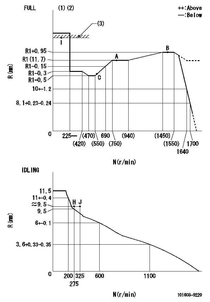
N:Pump speed
R:Rack position (mm)
(1)Torque cam stamping: T1
(2)Tolerance for racks not indicated: +-0.05mm.
(3)RACK LIMIT
----------
T1=L95
----------
----------
T1=L95
----------
Speed control lever angle

F:Full speed
I:Idle
(1)Use the hole at R = aa
(2)Stopper bolt set position 'H'
----------
aa=100mm
----------
a=26.5deg+-5deg b=(46deg)+-3deg
----------
aa=100mm
----------
a=26.5deg+-5deg b=(46deg)+-3deg
Stop lever angle
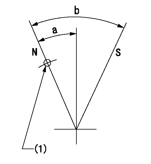
N:Pump normal
S:Stop the pump.
(1)Use the pin at R = aa
----------
aa=42mm
----------
a=25deg+-5deg b=40deg+-5deg
----------
aa=42mm
----------
a=25deg+-5deg b=40deg+-5deg
Timing setting

(1)Pump vertical direction
(2)Position of timer's threaded hole at No 1 cylinder's beginning of injection
(3)-
(4)-
----------
----------
a=(60deg)
----------
----------
a=(60deg)
Information:
GENERAL
Specification
Construction
Governor System Component Parts(1) Sealing metal(2) Sealing wire(3) Low- and high-speed(4) Governor spring(5) Sliding shaft(6) Stopper(7) Governor spring(8) Governor shaft(9) Governor lever(10) Tie-rod(11) Tie-rod clip(12) Tie-rod cover(13) tie-rod cover gasket(14) Tension lever(15) Start spring(16) Governor spring lever(17) Speed control lever assembly(18) Cover assembly(19) Governor cover gasket(20) Return spring(21) Stop lever assembly(22) O-ring(23) Snap ring(24) Stop lever(25) Grooved pin (3 x 20)(26) Grooved pin (3 x 14)(27) Torque spring set(28) Sealing capTORQUE SPRING
Installation of Torque Spring Set
Install and adjust the torque spring set using the following procedure:(1) Set the speed control lever to the high-idling speed position by adjusting the high-speed set bolt.(2) Turn in the torque spring set until engine speed drops about 50 rpm from high-idling speed.(3) From this position, turn back the torque spring set by the specified number of turns (N.) Lock the torque spring set at that position with the special nut.(4) Install the torque spring set sealing cap and stake the cap to prevent loosening. CAUTION There are two types of torque spring set: The single spring type and the double-spring type. Since each torque spring set has been adjusted precisely during assembly, do not tamper with the adjust screw unless it is necessary.
Torque spring setAssembling the Torque Spring Set
When the torque spring set has been disassembled or its component parts have been replaced, reassemble and adjust the torque spring set using the following procedure:
Assembling torque spring setSingle spring type
When installing the single-spring type torque spring set, use the following steps.(1) Lightly turn in adjust screw (5) (with a screw-driver operated by fingertips) until a resistance to screw rotation is felt. Lightly lock the screw at that position with locknut (4).(2) Set the scale to the zero-point. Turn in the spring case (2) until the value of load "A" shown in table below can be attained. Lock the spring case at that position with special nut (3).(3) Temporarily loosen adjust screw (5) until the value of load "A" is reduced by about 200 grams, and then retighten the screw until the value of "B" is attained. Lock the screw at that position with locknut (4).Adjust screw tightening torque: 0.8 to 1.2 kg.(4) To inspect the torque spring set for properly adjusted spring load, use a testing arrangement such as shown in the figure at right. Gradually push the scale against the torque spring set until the stopper (1) is moved (or the pointer of dial gauge deflects). Check that the load applied to the torque spring at that moment coincides with the value of load "C".
Setting of Torque Spring CHECKING
Replace the gear case and inspect the governor. When removing the gear case, be sure to remove the tie-rod cover by the side of the fuel pump and disconnect the tie-rod from the rack.If any parts are found defective, replace them.
Inspecting Torque Spring CAUTION When the governor is assumed to be malfunctioning, check the bearing on the gear case side, too.
Inspection Governor System PartsRemoval and Installation
(Refer to I-06 GEAR CASE AND OIL PUMP.)Removal(1) Removing