Information injection-pump assembly
ZEXEL
101608-9210
1016089210
NISSAN-DIESEL
16713Z6663
16713z6663
Rating:
Cross reference number
ZEXEL
101608-9210
1016089210
NISSAN-DIESEL
16713Z6663
16713z6663
Zexel num
Bosch num
Firm num
Name
Calibration Data:
Adjustment conditions
Test oil
1404 Test oil ISO4113 or {SAEJ967d}
1404 Test oil ISO4113 or {SAEJ967d}
Test oil temperature
degC
40
40
45
Nozzle and nozzle holder
105780-8260
Bosch type code
9 430 610 133
Nozzle
105780-0120
Bosch type code
1 688 901 990
Nozzle holder
105780-2190
Opening pressure
MPa
18
Opening pressure
kgf/cm2
184
Injection pipe
Outer diameter - inner diameter - length (mm) mm 6-2-600
Outer diameter - inner diameter - length (mm) mm 6-2-600
Overflow valve
131425-0420
Overflow valve opening pressure
kPa
157
123
191
Overflow valve opening pressure
kgf/cm2
1.6
1.25
1.95
Tester oil delivery pressure
kPa
255
255
255
Tester oil delivery pressure
kgf/cm2
2.6
2.6
2.6
Direction of rotation (viewed from drive side)
Right R
Right R
Injection timing adjustment
Direction of rotation (viewed from drive side)
Right R
Right R
Injection order
1-4-2-6-
3-5
Pre-stroke
mm
3.7
3.65
3.75
Beginning of injection position
Drive side NO.1
Drive side NO.1
Difference between angles 1
Cal 1-4 deg. 60 59.5 60.5
Cal 1-4 deg. 60 59.5 60.5
Difference between angles 2
Cyl.1-2 deg. 120 119.5 120.5
Cyl.1-2 deg. 120 119.5 120.5
Difference between angles 3
Cal 1-6 deg. 180 179.5 180.5
Cal 1-6 deg. 180 179.5 180.5
Difference between angles 4
Cal 1-3 deg. 240 239.5 240.5
Cal 1-3 deg. 240 239.5 240.5
Difference between angles 5
Cal 1-5 deg. 300 299.5 300.5
Cal 1-5 deg. 300 299.5 300.5
Injection quantity adjustment
Adjusting point
-
Rack position
11.7
Pump speed
r/min
800
800
800
Average injection quantity
mm3/st.
92
90.4
93.6
Max. variation between cylinders
%
0
-3.5
3.5
Basic
*
Fixing the rack
*
Standard for adjustment of the maximum variation between cylinders
*
Injection quantity adjustment_02
Adjusting point
Z
Rack position
9.5+-0.5
Pump speed
r/min
265
265
265
Average injection quantity
mm3/st.
9
7.2
10.8
Max. variation between cylinders
%
0
-10
10
Fixing the rack
*
Standard for adjustment of the maximum variation between cylinders
*
Injection quantity adjustment_03
Adjusting point
A
Rack position
R1(11.7)
Pump speed
r/min
800
800
800
Average injection quantity
mm3/st.
92
91
93
Basic
*
Fixing the lever
*
Injection quantity adjustment_04
Adjusting point
B
Rack position
R1+0.95
Pump speed
r/min
1500
1500
1500
Average injection quantity
mm3/st.
97.5
93.5
101.5
Fixing the lever
*
Injection quantity adjustment_05
Adjusting point
C
Rack position
(R1-0.35
)
Pump speed
r/min
600
600
600
Average injection quantity
mm3/st.
86.5
82.5
90.5
Fixing the lever
*
Injection quantity adjustment_06
Adjusting point
I
Rack position
-
Pump speed
r/min
100
100
100
Average injection quantity
mm3/st.
105
105
115
Fixing the lever
*
Rack limit
*
Timer adjustment
Pump speed
r/min
(900)
Advance angle
deg.
0
0
0
Remarks
Start
Start
Timer adjustment_02
Pump speed
r/min
1080
Advance angle
deg.
2
1.5
2.5
Timer adjustment_03
Pump speed
r/min
1225
Advance angle
deg.
2
1.5
2.5
Timer adjustment_04
Pump speed
r/min
1425
Advance angle
deg.
6
5.5
6.5
Remarks
Finish
Finish
Test data Ex:
Governor adjustment
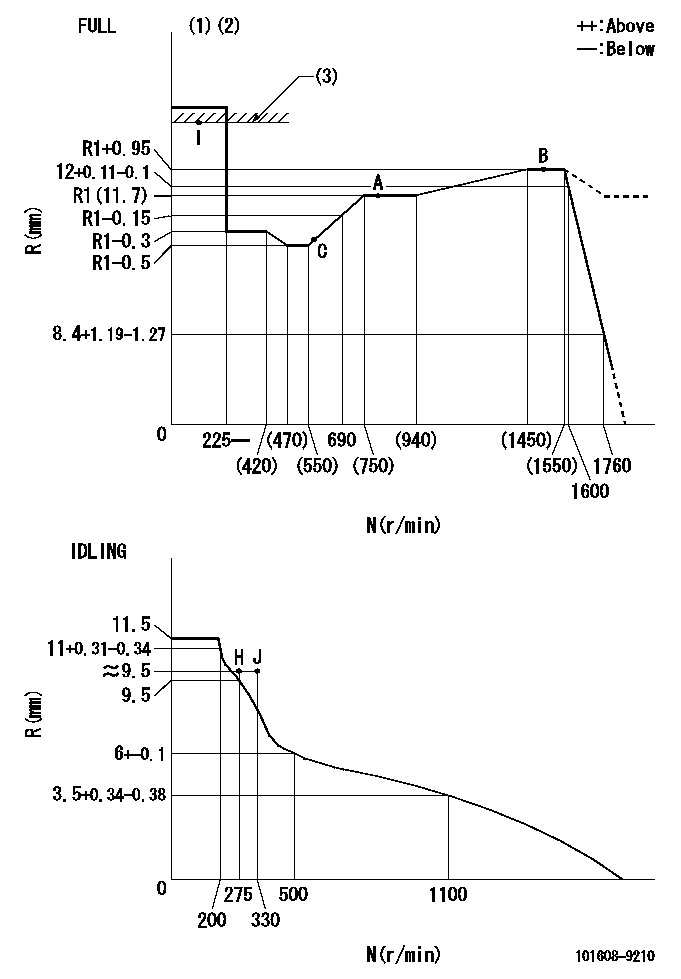
N:Pump speed
R:Rack position (mm)
(1)Torque cam stamping: T1
(2)Tolerance for racks not indicated: +-0.05mm.
(3)RACK LIMIT
----------
T1=L78
----------
----------
T1=L78
----------
Speed control lever angle

F:Full speed
I:Idle
(1)Use the hole at R = aa
(2)Stopper bolt set position 'H'
----------
aa=39mm
----------
a=20deg+-5deg b=42deg+-3deg
----------
aa=39mm
----------
a=20deg+-5deg b=42deg+-3deg
Stop lever angle
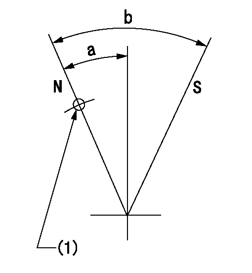
N:Pump normal
S:Stop the pump.
(1)Use the pin at R = aa
----------
aa=42mm
----------
a=25deg+-5deg b=40deg+-5deg
----------
aa=42mm
----------
a=25deg+-5deg b=40deg+-5deg
0000001501 LEVER
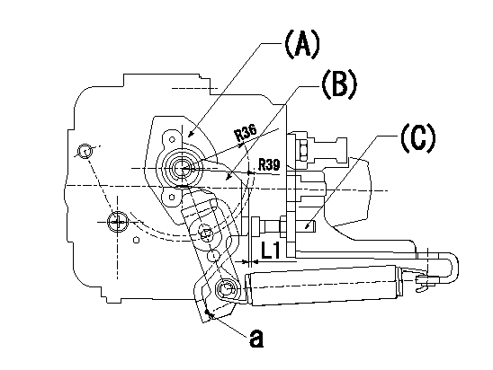
(a) Speed lever
(B) Accelerator lever
(C) Accelerator lever stopper bolt
1. Accelerator lever setting method
With the speed lever in the idling position, back off the accelerator lever stopper bolt L1 from where it contacts point a. (Back off 1+0.5 turns and set.)
----------
L1=1+0.5mm
----------
----------
L1=1+0.5mm
----------
Timing setting

(1)Pump vertical direction
(2)Position of timer's threaded hole at No 1 cylinder's beginning of injection
(3)-
(4)-
----------
----------
a=(60deg)
----------
----------
a=(60deg)
Information:
GENERAL
Specifications
Components parts
Fuel System Component Parts(1) Injection pump(2) Adjustment shim(3) Injection pipe(4) Injection nozzle(5) Return pipe(6) Fuel filter(7) Fuel cutoff solenoidFUEL INJECTION PUMP
Construction
Injection Pump Component Parts(1) Union collar(2) Air vent screw(3) Delivery valve holder(4) Valve spring(5) Holder stopper(6) Housing(7) O-ring(8) Delivery valve(9) Gasket(10) Seat valve(11) Plunger barrel(12) Sleeve(13) Upper seat(14) Plunger spring(15) Plunger(16) Lower seat(17) Adjusting shim(18) Tappet roller(19) Pin(20) Control rack(21) Stop wire bracketInspecting the injection pump while it is mounted on the engine
Never attempt to disassemble the pump unless it is necessary.If the pump is assumed defective, it is recommended to replace the pump assembly. Removal
(1) Disconnect the fuel injection pipes.(2) Remove the tie-rod clip cover.(3) Remove the tie-rod clip and tie-rod.(4) Remove the injection pump assembly.
Removing Injection PumpDisassembly
(1) Remove the stopper plate.(2) Unscrew the delivery holder. Take out the delivery valve and valve spring.(3) Remove the tappet roller and stopper pin.(4) Remove the tappet, plunger spring, etc. CAUTION1. When replacing the plunger barrel, delivery valve, etc., do not loosen the adjusting screw and plate for each cylinder.2. When those parts have been replaced, it is necessary to measure fuel injection quantity by using the pump tester and cam box.3. All parts removed from the pump should be kept classified by cylinders and immersed in clean fuel.Inspection
Inspection of Injection PumpAssembly
(1) Insert the plunger barrel into the housing.(2) Install the delivery valve and valve spring. Temporarily tighten the holder.(3) Insert the control rack.(4) Insert the control pinion. Align the matchmark on the rack with that on the pinion.(5) Install the spring upper seat.(6) Insert the plunger spring.(7) Fit the lower seat to the plunger. Insert the plunger into the barrel side.(8) Depress the tappet roller assembly and install the stopper pin.(9) Tighten the delivery holder. Tightening torque : 3.5 - 3.9 kgm
Direction of Installation of PlungerInstallation
Install the injection pump assembly in the reverse order of removal. CAUTION* When installing the plunger barrel, engage the dowel pin on the housing side with the groove in the barrel.* Position the plunger so that the part-number stamp on its flanges faces the direction opposite to the rack side. (Engage the feed hole with the plunger lead.)* After installation, check for proper injection timing.INJECTION NOZZLE
Construction
Nozzle Holder Ass'y Component Parts(1) Body sub-assembly(2) Shim washer(3) Pressure spring(4) Pin(5) Distance piece(6) Nozzle assembly(7) Retaining nutRemoval
(1) Disconnect the injection pipe and fuel return pipe.(2) Remove the injection nozzle assembly from the cylinder head. CAUTION* Attach an identification-number tag to the removed injection nozzle.* Plug the openings, from which the pipes are disconnected and the nozzle is removed, to prevent intrusion of dust, water, and other foreign particles into the pipes and combustion chamber.Disassembly
If the removed nozzle assembly is assumed defective, disassemble the assembly and repair or replace the faulty parts.(1) Grip the nozzle holder body in a vise. Loosen the retaining nut. Never vise the retaining nut to prevent deformation.(2) Take out the shim washer, pressure spring, distance piece, and nozzle assembly. CAUTION* Scrape off carbon deposit with a wooden spatula. Keep the removed parts immersed