Information injection-pump assembly
BOSCH
F 01G 09U 065
f01g09u065
ZEXEL
101608-9151
1016089151
NISSAN-DIESEL
1671395304
1671395304
Rating:
Include in #2:
104140-3040
as _
Cross reference number
BOSCH
F 01G 09U 065
f01g09u065
ZEXEL
101608-9151
1016089151
NISSAN-DIESEL
1671395304
1671395304
Zexel num
Bosch num
Firm num
Name
F 01G 09U 065
1671395304 NISSAN-DIESEL
INJECTION-PUMP ASSEMBLY
NE6TA * K 14BF PE6AD PE
NE6TA * K 14BF PE6AD PE
Calibration Data:
Adjustment conditions
Test oil
1404 Test oil ISO4113 or {SAEJ967d}
1404 Test oil ISO4113 or {SAEJ967d}
Test oil temperature
degC
40
40
45
Nozzle and nozzle holder
105780-8140
Bosch type code
EF8511/9A
Nozzle
105780-0000
Bosch type code
DN12SD12T
Nozzle holder
105780-2080
Bosch type code
EF8511/9
Opening pressure
MPa
17.2
Opening pressure
kgf/cm2
175
Injection pipe
Outer diameter - inner diameter - length (mm) mm 6-2-600
Outer diameter - inner diameter - length (mm) mm 6-2-600
Overflow valve
131424-1520
Overflow valve opening pressure
kPa
157
123
191
Overflow valve opening pressure
kgf/cm2
1.6
1.25
1.95
Tester oil delivery pressure
kPa
157
157
157
Tester oil delivery pressure
kgf/cm2
1.6
1.6
1.6
Direction of rotation (viewed from drive side)
Right R
Right R
Injection timing adjustment
Direction of rotation (viewed from drive side)
Right R
Right R
Injection order
1-4-2-6-
3-5
Pre-stroke
mm
3.9
3.85
3.95
Beginning of injection position
Drive side NO.1
Drive side NO.1
Difference between angles 1
Cal 1-4 deg. 60 59.5 60.5
Cal 1-4 deg. 60 59.5 60.5
Difference between angles 2
Cyl.1-2 deg. 120 119.5 120.5
Cyl.1-2 deg. 120 119.5 120.5
Difference between angles 3
Cal 1-6 deg. 180 179.5 180.5
Cal 1-6 deg. 180 179.5 180.5
Difference between angles 4
Cal 1-3 deg. 240 239.5 240.5
Cal 1-3 deg. 240 239.5 240.5
Difference between angles 5
Cal 1-5 deg. 300 299.5 300.5
Cal 1-5 deg. 300 299.5 300.5
Injection quantity adjustment
Adjusting point
-
Rack position
13.8
Pump speed
r/min
1400
1400
1400
Average injection quantity
mm3/st.
118
116.4
119.6
Max. variation between cylinders
%
0
-3.5
3.5
Basic
*
Fixing the rack
*
Standard for adjustment of the maximum variation between cylinders
*
Injection quantity adjustment_02
Adjusting point
-
Rack position
9.6+-0.5
Pump speed
r/min
275
275
275
Average injection quantity
mm3/st.
9
7.2
10.8
Max. variation between cylinders
%
0
-10
10
Fixing the rack
*
Standard for adjustment of the maximum variation between cylinders
*
Remarks
Adjust only variation between cylinders; adjust governor according to governor specifications.
Adjust only variation between cylinders; adjust governor according to governor specifications.
Injection quantity adjustment_03
Adjusting point
A
Rack position
R1(13.8)
Pump speed
r/min
1400
1400
1400
Average injection quantity
mm3/st.
118
117
119
Basic
*
Fixing the lever
*
Boost pressure
kPa
43.3
43.3
Boost pressure
mmHg
325
325
Injection quantity adjustment_04
Adjusting point
B
Rack position
R1-0.8
Pump speed
r/min
900
900
900
Average injection quantity
mm3/st.
94.5
91.3
97.7
Fixing the lever
*
Boost pressure
kPa
43.3
43.3
Boost pressure
mmHg
325
325
Injection quantity adjustment_05
Adjusting point
C
Rack position
R2-0.95
Pump speed
r/min
600
600
600
Average injection quantity
mm3/st.
59.5
55.5
63.5
Fixing the lever
*
Boost pressure
kPa
0
0
0
Boost pressure
mmHg
0
0
0
Injection quantity adjustment_06
Adjusting point
I
Rack position
-
Pump speed
r/min
150
150
150
Average injection quantity
mm3/st.
80
80
100
Fixing the lever
*
Boost pressure
kPa
0
0
0
Boost pressure
mmHg
0
0
0
Rack limit
*
Boost compensator adjustment
Pump speed
r/min
600
600
600
Rack position
R2-0.95
Boost pressure
kPa
14
12.7
15.3
Boost pressure
mmHg
105
95
115
Boost compensator adjustment_02
Pump speed
r/min
600
600
600
Rack position
R2(R1-1.
2)
Boost pressure
kPa
30
30
30
Boost pressure
mmHg
225
225
225
Timer adjustment
Pump speed
r/min
920--
Advance angle
deg.
0
0
0
Remarks
Start
Start
Timer adjustment_02
Pump speed
r/min
870
Advance angle
deg.
0.5
Timer adjustment_03
Pump speed
r/min
1400
Advance angle
deg.
2
1.5
2.5
Remarks
Finish
Finish
Test data Ex:
Governor adjustment
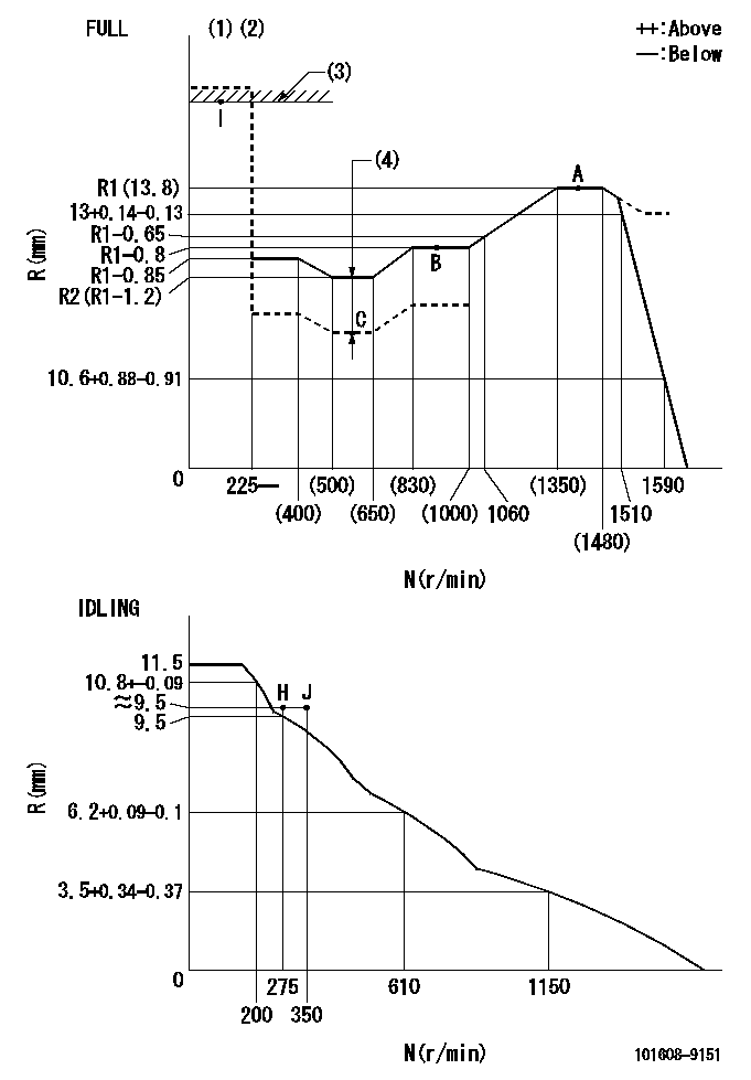
N:Pump speed
R:Rack position (mm)
(1)Torque cam stamping: T1
(2)Tolerance for racks not indicated: +-0.05mm.
(3)RACK LIMIT
(4)Boost compensator stroke: BCL
----------
T1=J98 BCL=0.95+-0.1mm
----------
----------
T1=J98 BCL=0.95+-0.1mm
----------
Speed control lever angle

F:Full speed
I:Idle
(1)Use the hole at R = aa
(2)Stopper bolt set position 'H'
----------
aa=100mm
----------
a=26.5deg+-5deg b=42deg+-3deg
----------
aa=100mm
----------
a=26.5deg+-5deg b=42deg+-3deg
Stop lever angle
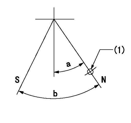
N:Pump normal
S:Stop the pump.
(1)Use the hole at R = aa
----------
aa=36mm
----------
a=20deg+-5deg b=40deg+-5deg
----------
aa=36mm
----------
a=20deg+-5deg b=40deg+-5deg
Timing setting

(1)Pump vertical direction
(2)Coupling's key groove position at No 1 cylinder's beginning of injection
(3)-
(4)-
----------
----------
a=(30deg)
----------
----------
a=(30deg)
Information:
Setting rack(4) Setting governor (setting maximum speed )(a) While applying the full load to the engine, hold the speed control lever in the specified maximum speed position.(b) Adjust the governor setting bolt (maximum speed setting bolt) to the specified speed position, and set it there.
Setting governor(5) Setting torque spring (optional specification)Set the speed control lever at the maximum speed, and apply the load to the engine. Turn the torque spring adjusting screw until the engine delivers the specified output at the specified speed. Fix the screw with the locknut, and install a cap to the lock nut.
Setting torque spring(6) Measuring speed variationMeasurement of speed variation at removal of load.(a) Operate the speed control to set the engine at the rated output and speed.(b) From this condition, instantaneously remove the load to put the engine into the no-load condition. Operate the engine with the speed control lever fixed.(c) The engine speed temporarily jumps up then lowers and stabilizes. Record the momentary maximum speed, stabilized speed, and time from the removal of the load to the stabilization of the speed.Measurement of speed variation at application of load.From the no-load condition, instantaneously apply the specified load to the engine. Record the momentary maximum speed, stabilized speed, and time from the application of the load to the stabilization of the speed.Calculation of speed variationCalculate the speed variation from the measured results. When the speed variation falls outside specified limits, adjust the governor notches.
Measuring speed variation(7) Adjusting speed variation (adjusting governor notches)(a) Adjust the speed variation by turning the adjusting screw of the swivel lever.(b) Remove the plug at the top of the governor, and set the speed control lever to the low idle speed position. The swivel lever turns up to reveal the head of the adjusting screw. Turn the adjusting screw with a flat-head screwdriver.(c) The speed variation decreases as the adjusting screw is tightened and increases as the adjusting screw is loosened. One notch equals a quarter turn of the adjusting screw and changes the engine speed by three to five revolutions.(d) Turning the adjusting screw changes the governor spring tension and hence the maximum speed. Readjust the governor setting bolt.(e) The maximum speed increases as the adjusting screw is tightened and decreases as the adjusting screw is loosened.
The adjusting screw can be loosened by 20 notches (or five turns) from the position where it is fully tightened. It is dangerous if the adjusting screw is loosened more.
Adjusting speed variation(8) SealingSeal each setting bolt.Break-in Operation
When the engine is overhauled, it should be mounted on a dynamometer and operated for break-in and inspection.Starting Up
(1) Before starting the engine, check the levels of coolant, engine oil and fuel, and bleed the fuel and cooling system.(2) With the fuel supply cut off, operate the starter and crank the engine for about 15 seconds to circulate engine oil.(3) Move the speed control lever slightly in the direction for increased fuel (do not move it to "full injection" position), and then turn the starter switch