Information injection-pump assembly
BOSCH
F 01G 09U 064
f01g09u064
ZEXEL
101608-9150
1016089150
NISSAN-DIESEL
1671395302
1671395302
Rating:
Include in #2:
105856-2520
as _
Cross reference number
BOSCH
F 01G 09U 064
f01g09u064
ZEXEL
101608-9150
1016089150
NISSAN-DIESEL
1671395302
1671395302
Zexel num
Bosch num
Firm num
Name
Calibration Data:
Adjustment conditions
Test oil
1404 Test oil ISO4113 or {SAEJ967d}
1404 Test oil ISO4113 or {SAEJ967d}
Test oil temperature
degC
40
40
45
Nozzle and nozzle holder
105780-8140
Bosch type code
EF8511/9A
Nozzle
105780-0000
Bosch type code
DN12SD12T
Nozzle holder
105780-2080
Bosch type code
EF8511/9
Opening pressure
MPa
17.2
Opening pressure
kgf/cm2
175
Injection pipe
Outer diameter - inner diameter - length (mm) mm 6-2-600
Outer diameter - inner diameter - length (mm) mm 6-2-600
Overflow valve
131424-1520
Overflow valve opening pressure
kPa
157
123
191
Overflow valve opening pressure
kgf/cm2
1.6
1.25
1.95
Tester oil delivery pressure
kPa
157
157
157
Tester oil delivery pressure
kgf/cm2
1.6
1.6
1.6
Direction of rotation (viewed from drive side)
Right R
Right R
Injection timing adjustment
Direction of rotation (viewed from drive side)
Right R
Right R
Injection order
1-4-2-6-
3-5
Pre-stroke
mm
3.9
3.85
3.95
Beginning of injection position
Drive side NO.1
Drive side NO.1
Difference between angles 1
Cal 1-4 deg. 60 59.5 60.5
Cal 1-4 deg. 60 59.5 60.5
Difference between angles 2
Cyl.1-2 deg. 120 119.5 120.5
Cyl.1-2 deg. 120 119.5 120.5
Difference between angles 3
Cal 1-6 deg. 180 179.5 180.5
Cal 1-6 deg. 180 179.5 180.5
Difference between angles 4
Cal 1-3 deg. 240 239.5 240.5
Cal 1-3 deg. 240 239.5 240.5
Difference between angles 5
Cal 1-5 deg. 300 299.5 300.5
Cal 1-5 deg. 300 299.5 300.5
Injection quantity adjustment
Adjusting point
-
Rack position
13.8
Pump speed
r/min
1400
1400
1400
Average injection quantity
mm3/st.
118
116.4
119.6
Max. variation between cylinders
%
0
-3.5
3.5
Basic
*
Fixing the rack
*
Standard for adjustment of the maximum variation between cylinders
*
Injection quantity adjustment_02
Adjusting point
-
Rack position
9.6+-0.5
Pump speed
r/min
275
275
275
Average injection quantity
mm3/st.
9
7.2
10.8
Max. variation between cylinders
%
0
-10
10
Fixing the rack
*
Standard for adjustment of the maximum variation between cylinders
*
Remarks
Adjust only variation between cylinders; adjust governor according to governor specifications.
Adjust only variation between cylinders; adjust governor according to governor specifications.
Injection quantity adjustment_03
Adjusting point
A
Rack position
R1(13.8)
Pump speed
r/min
1400
1400
1400
Average injection quantity
mm3/st.
118
117
119
Basic
*
Fixing the lever
*
Boost pressure
kPa
33.3
33.3
Boost pressure
mmHg
250
250
Injection quantity adjustment_04
Adjusting point
B
Rack position
R1-0.8
Pump speed
r/min
900
900
900
Average injection quantity
mm3/st.
94.5
91.3
97.7
Fixing the lever
*
Boost pressure
kPa
33.3
33.3
Boost pressure
mmHg
250
250
Injection quantity adjustment_05
Adjusting point
C
Rack position
R2-0.75
Pump speed
r/min
600
600
600
Average injection quantity
mm3/st.
60.5
56.5
64.5
Fixing the lever
*
Boost pressure
kPa
0
0
0
Boost pressure
mmHg
0
0
0
Injection quantity adjustment_06
Adjusting point
I
Rack position
-
Pump speed
r/min
150
150
150
Average injection quantity
mm3/st.
80
80
100
Fixing the lever
*
Boost pressure
kPa
0
0
0
Boost pressure
mmHg
0
0
0
Rack limit
*
Boost compensator adjustment
Pump speed
r/min
600
600
600
Rack position
R2-0.75
Boost pressure
kPa
7.3
6
8.6
Boost pressure
mmHg
55
45
65
Boost compensator adjustment_02
Pump speed
r/min
600
600
600
Rack position
R2(R1-1.
2)
Boost pressure
kPa
20
20
20
Boost pressure
mmHg
150
150
150
Timer adjustment
Pump speed
r/min
920--
Advance angle
deg.
0
0
0
Remarks
Start
Start
Timer adjustment_02
Pump speed
r/min
870
Advance angle
deg.
0.5
Timer adjustment_03
Pump speed
r/min
1400
Advance angle
deg.
2
1.5
2.5
Remarks
Finish
Finish
Test data Ex:
Governor adjustment
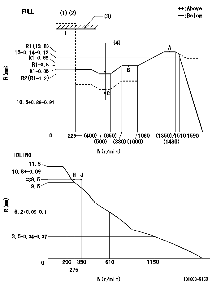
N:Pump speed
R:Rack position (mm)
(1)Torque cam stamping: T1
(2)Tolerance for racks not indicated: +-0.05mm.
(3)RACK LIMIT
(4)Boost compensator stroke: BCL
----------
T1=J98 BCL=0.75+-0.1mm
----------
----------
T1=J98 BCL=0.75+-0.1mm
----------
Speed control lever angle

F:Full speed
I:Idle
(1)Use the hole at R = aa
(2)Stopper bolt set position 'H'
----------
aa=100mm
----------
a=26.5deg+-5deg b=42deg+-3deg
----------
aa=100mm
----------
a=26.5deg+-5deg b=42deg+-3deg
Stop lever angle
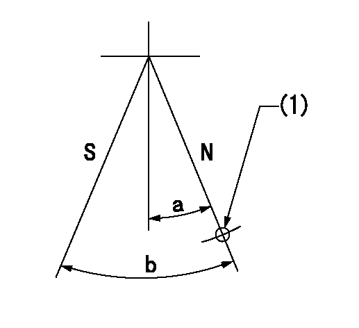
N:Pump normal
S:Stop the pump.
(1)Use the hole at R = aa
----------
aa=36mm
----------
a=20deg+-5deg b=40deg+-5deg
----------
aa=36mm
----------
a=20deg+-5deg b=40deg+-5deg
Timing setting

(1)Pump vertical direction
(2)Coupling's key groove position at No 1 cylinder's beginning of injection
(3)-
(4)-
----------
----------
a=(30deg)
----------
----------
a=(30deg)
Information:
No-load testAlternator
If a problem occurs in the charge system, check the following conditions to locate the cause of the problem. Only when inspection cannot be conducted on the alternator in the installed condition, dismount the alternator for inspection and repair. On Vehicle Inspection
(1) Cautions for handlingHandle the alternator carefully, as incorrect handling can result in alternator damage or malfunctions.(a) Do not connect the battery cables in reverse. Note the negative (-) cable is a grounding wire.(b) Do not use a high-voltage tester such as a megger.(c) When charging the battery, disconnect the cables from the battery terminals.(d) Do not disconnect the lead wire from terminal B of the alternator while the engine is operating.(e) Do not ground terminal B of the alternator since it is constantly applied with battery voltage.(f) Do not short-circuit or ground terminal L. (unit with integrated IC regulator)(g) When using a steam cleaner, do not allow steam to directly contact the alternator.(2) Inspection of adjustment voltage (unit with integrated IC regulator)(a) Disconnect the cable from the positive (+) terminal of the battery, and connect an ammeter between the terminal and cable.(b) Connect a voltmeter between terminal L and ground.(c) Make sure that the voltmeter indicates "0" when the starter switch is turned off. Make sure that the voltmeter indicates a voltage level significantly lower than the battery voltage when the starter switch is turned on (without starting the engine).(d) Short-circuit the terminal of the ammeter, and start the engine.(e) Read the indication (adjustment voltage) on the voltmeter with the ammeter indicating 5A or lower, the engine operating at 1500 to 2500 min-1, and the lamp switches turned off.
Inspection of adjustment voltage (3) Inspection of output (unit with integrated IC regulator)(a) Disconnect the grounding cable from the battery.(b) Disconnect the wire from terminal B of the alternator, and connect an ammeter, then connect a voltmeter between B and ground.(c) Reconnect the grounding cable to the battery.(d) Start the engine.(e) Immediately after the engine starts, turn on all load devices such as lamps.(f) Increase the engine speed, and read the maximum current at the specified alternator rotation speed when the voltmeter indicates 27.0 V. If the measured value conforms to the standard value, the alternator is normal.
Wiring for output test (unit with integrated IC regulator) Disassembly of Alternator
(1) Separation of front bracket from stator coreInsert the tip of a slotted screwdriver into the gap between the stator core and front bracket, and pry open.
Do not insert the screwdriver too far into the assembly to prevent damaging the stator core.
Separation of front bracket from stator core(2) Removal of pulley(a) After wrapping the rotor with a cloth for protection and holding it with a vice, unscrew the pulley nut, then remove the pulley and spacer.(b) Remove the rotor from the front bracket.
Removal of pulley(3) Removal of stator core and rectifier(a) Disconnect the lead wires between the stator core and the rectifier at the soldered sections, and remove the stator core.
Melt the soldered sections as quickly as possible. Prolonged