Information injection-pump assembly
BOSCH
F 019 Z20 024
f019z20024
ZEXEL
101608-6462
1016086462
MITSUBISHI
ME441276
me441276
Rating:
Include in #2:
104749-0820
as _
Cross reference number
BOSCH
F 019 Z20 024
f019z20024
ZEXEL
101608-6462
1016086462
MITSUBISHI
ME441276
me441276
Zexel num
Bosch num
Firm num
Name
101608-6462
F 019 Z20 024
ME441276 MITSUBISHI
INJECTION-PUMP ASSEMBLY
6D16TL K 14BN INJECTION PUMP ASSY PE
6D16TL K 14BN INJECTION PUMP ASSY PE
Calibration Data:
Adjustment conditions
Test oil
1404 Test oil ISO4113 or {SAEJ967d}
1404 Test oil ISO4113 or {SAEJ967d}
Test oil temperature
degC
40
40
45
Nozzle and nozzle holder
105780-8140
Bosch type code
EF8511/9A
Nozzle
105780-0000
Bosch type code
DN12SD12T
Nozzle holder
105780-2080
Bosch type code
EF8511/9
Opening pressure
MPa
17.2
Opening pressure
kgf/cm2
175
Injection pipe
Outer diameter - inner diameter - length (mm) mm 6-2-600
Outer diameter - inner diameter - length (mm) mm 6-2-600
Overflow valve
131424-5520
Overflow valve opening pressure
kPa
255
221
289
Overflow valve opening pressure
kgf/cm2
2.6
2.25
2.95
Tester oil delivery pressure
kPa
255
255
255
Tester oil delivery pressure
kgf/cm2
2.6
2.6
2.6
Direction of rotation (viewed from drive side)
Left L
Left L
Injection timing adjustment
Direction of rotation (viewed from drive side)
Left L
Left L
Injection order
1-5-3-6-
2-4
Pre-stroke
mm
4.5
4.45
4.55
Beginning of injection position
Governor side NO.1
Governor side NO.1
Difference between angles 1
Cal 1-5 deg. 60 59.5 60.5
Cal 1-5 deg. 60 59.5 60.5
Difference between angles 2
Cal 1-3 deg. 120 119.5 120.5
Cal 1-3 deg. 120 119.5 120.5
Difference between angles 3
Cal 1-6 deg. 180 179.5 180.5
Cal 1-6 deg. 180 179.5 180.5
Difference between angles 4
Cyl.1-2 deg. 240 239.5 240.5
Cyl.1-2 deg. 240 239.5 240.5
Difference between angles 5
Cal 1-4 deg. 300 299.5 300.5
Cal 1-4 deg. 300 299.5 300.5
Injection quantity adjustment
Adjusting point
A
Rack position
11.1
Pump speed
r/min
1200
1200
1200
Average injection quantity
mm3/st.
103.5
102.5
104.5
Max. variation between cylinders
%
0
-2.5
2.5
Basic
*
Fixing the lever
*
Boost pressure
kPa
54.7
54.7
Boost pressure
mmHg
410
410
Injection quantity adjustment_02
Adjusting point
-
Rack position
9.1+-0.5
Pump speed
r/min
300
300
300
Average injection quantity
mm3/st.
16.5
15
18
Max. variation between cylinders
%
0
-15
15
Fixing the rack
*
Boost pressure
kPa
0
0
0
Boost pressure
mmHg
0
0
0
Remarks
Adjust only variation between cylinders; adjust governor according to governor specifications.
Adjust only variation between cylinders; adjust governor according to governor specifications.
Injection quantity adjustment_03
Adjusting point
E
Rack position
11.3++
Pump speed
r/min
100
100
100
Average injection quantity
mm3/st.
145
145
155
Fixing the lever
*
Boost pressure
kPa
0
0
0
Boost pressure
mmHg
0
0
0
Rack limit
*
Boost compensator adjustment
Pump speed
r/min
400
400
400
Rack position
9.65
Boost pressure
kPa
16
13.3
18.7
Boost pressure
mmHg
120
100
140
Boost compensator adjustment_02
Pump speed
r/min
400
400
400
Rack position
10.7
Boost pressure
kPa
41.3
34.6
48
Boost pressure
mmHg
310
260
360
Timer adjustment
Pump speed
r/min
0
Advance angle
deg.
3
2.5
3.5
Load
0/4
Timer adjustment_02
Pump speed
r/min
550+50
Advance angle
deg.
3
2.5
3.5
Load
0/4
Remarks
Start
Start
Timer adjustment_03
Pump speed
r/min
650-50
Advance angle
deg.
0
0
0
Load
0/4
Remarks
Finish
Finish
Test data Ex:
Governor adjustment
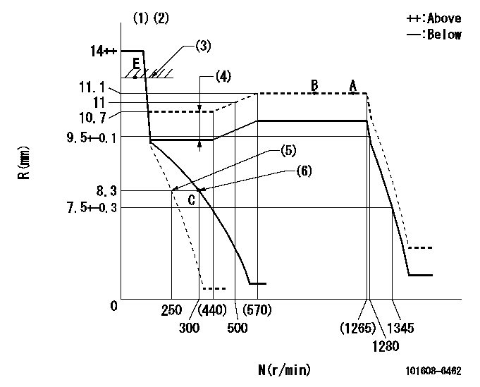
N:Pump speed
R:Rack position (mm)
(1)Target notch: K
(2)Tolerance for racks not indicated: +-0.05mm.
(3)RACK LIMIT
(4)Boost compensator stroke: BCL
(5)Set idle sub-spring
(6)Main spring setting
----------
K=14 BCL=1.05+-0.1mm
----------
----------
K=14 BCL=1.05+-0.1mm
----------
Speed control lever angle
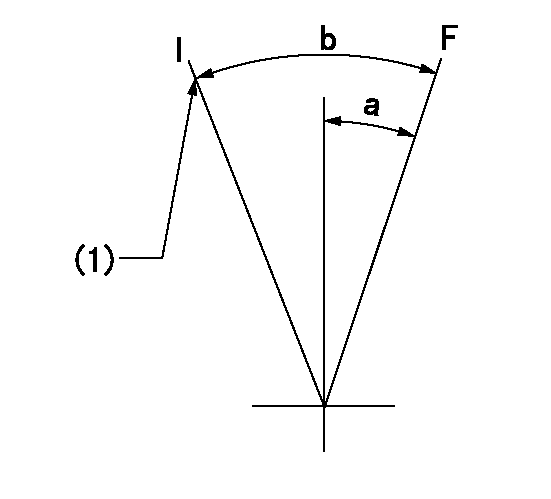
F:Full speed
I:Idle
(1)Stopper bolt setting
----------
----------
a=(12.5deg)+-5deg b=(26.5deg)+-5deg
----------
----------
a=(12.5deg)+-5deg b=(26.5deg)+-5deg
Stop lever angle
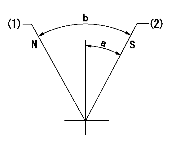
N:Pump normal
S:Stop the pump.
(1)Normal
(2)Pump speed aa and rack position bb (to be sealed at delivery)
----------
aa=0r/min bb=4-0.5mm
----------
a=28deg+-5deg b=(48deg)
----------
aa=0r/min bb=4-0.5mm
----------
a=28deg+-5deg b=(48deg)
0000001501 TAMPER PROOF

Tamperproofing-equipped boost compensator cover installation procedure
(A) After adjusting the boost compensator, tighten the bolts to remove the heads.
(1)Before adjusting the governor and the boost compensator, tighten the screw to the specified torque.
(Tightening torque T = T1 maximum)
(2)After adjusting the governor and the boost compensator, tighten to the specified torque to break off the bolt heads.
(Tightening torque T = T2)
----------
T1=2.5N-m(0.25kgf-m) T2=2.9~4.4N-m(0.3~0.45kgf-m)
----------
----------
T1=2.5N-m(0.25kgf-m) T2=2.9~4.4N-m(0.3~0.45kgf-m)
----------
Timing setting

(1)Pump vertical direction
(2)Coupling's key groove position at No 1 cylinder's beginning of injection
(3)B.T.D.C.: aa
(4)-
----------
aa=6deg
----------
a=(3deg)
----------
aa=6deg
----------
a=(3deg)
Information:
(5) Removing Alternator
(a) Disconnect the battery cables.(b) Disconnect the lead from terminal B at the rear of the alternator.(c) Remove the alternator connector.(d) Loose the alternator adjusting bolt (1) and support bolt (2), then push the alternator toward the engine and remove the fan belt.(e) Remove the alternator.
Removing alternator(6) Removing Starter
(a) Disconnect the battery's (-) and (+) terminals in that sequence.(b) Disconnect the starter wiring (1).(c) Remove the starter's two mounting bolts (2), then remove the starter (3).
Removing starter(7) Removing Oil Filter
(a) The oil filter (2) must be replaced every 100 hours of use.(b) Remove the oil filter using a filter wrench (1).
Removing oil filter(8) Removing Fuel Filter
(a) Remove the fuel hose (1) that leads to the fuel injection pump.(b) Remove the fuel filter (2) from the engine.
Removing fuel filter(9) Removing Fuel Pipes
(a) Remove the clamps from the four fuel pipes (1), then disconnect the fuel pipes from the engine and from the injection pump.(b) Remove the lock nuts (2) and the fuel leak-off pipe (3) from the injection nozzle.
Removing Fuel Pipes
To keep dirt out of the fuel system, fit rubber caps over the parts of the injection pump and injector inlet connectors from which the injection pipes are disconnected.
(10) Removing Injection Pump
Removing Injection Pump(1) Fuel hose(2) Fuel pipe(3) Tie rod cover(4) Tie rod spring(5) Tie rod(6) Injection pump(7) Adjustment shim(8) Control rack pin(a) Remove the tie rod cover (3).(b) Using long-nosed pliers, remove the tie rod spring (4) from the control rack pin (8) and from the governor lever pin.(c) Remove the tie rod (5).
Removing tie rod(d) Remove the injection pump (6) and the adjustment shim (7).
Removing injection pump(11) Removing ETS Solenoid
Loose the nut (1) and remove the ETS solenoid (2).
Removing ETS solenoid(12) Removing Oil Pump
Remove the oil pump's four mounting bolts, then remove the oil pump (1).
Removing oil pump(13) Removing Injection Nozzle
(a) Remove all lock nuts (1) (4 pieces).(b) Remove fuel leak-off pipe (2) and fuel return gasket (3).(c) Remove fuel injection nozzle (4) and holder gasket (5).
Removing injection nozzleRefitting Accessories
General Points
Refit accessories by following the removal procedures in reverse. After refitting accessories, perform the following:(1) Pour the specified amount of engine oil into the engine.(2) Pour coolant into the coolant system.(3) To facilitate starting, pour engine oil into the governor's hydraulic oil filter via the hole of the air bleeding plug.(4) Make sure no oil or coolant is leaking from joints and connections.(5) Air-bleed the fuel system.(6) After refitting the injection pump (see the instructions below), be sure to inspect and adjust the injection timing.Installing Injection Pump
Installation should be performed basically by following the removal procedure in reverse. The following operations must also be performed.(1) Bleeding Air from Fuel System
Bleeding air from fuel system(a) Feed fuel to the engine by turning the key to the ON position. Then, loosen the air vent screw (1), allow air in the filter to be expelled, and retighten the screw.(b) Loosen air vent screws (2) and (3) on the injection pump in that sequence to bleed air from the
Have questions with 101608-6462?
Group cross 101608-6462 ZEXEL
Mitsubishi
Mitsubishi
Mitsubishi
Mitsubishi
Mitsubishi
Mitsubishi
Mitsubishi
101608-6462
F 019 Z20 024
ME441276
INJECTION-PUMP ASSEMBLY
6D16TL
6D16TL