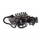
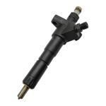
Information injection-pump assembly
BOSCH
9 400 613 472
9400613472
ZEXEL
101608-6432
1016086432
MITSUBISHI
ME441260
me441260
Rating:
Service parts 101608-6432 INJECTION-PUMP ASSEMBLY:
1.
_
7.
COUPLING PLATE
8.
_
9.
_
11.
Nozzle and Holder
12.
Open Pre:MPa(Kqf/cm2)
17.7{180}
15.
NOZZLE SET
Include in #1:
101608-6432
as INJECTION-PUMP ASSEMBLY
Include in #2:
104740-0850
as _
Cross reference number
BOSCH
9 400 613 472
9400613472
ZEXEL
101608-6432
1016086432
MITSUBISHI
ME441260
me441260
Zexel num
Bosch num
Firm num
Name
101608-6432
9 400 613 472
ME441260 MITSUBISHI
INJECTION-PUMP ASSEMBLY
6D16TL K 14BN INJECTION PUMP ASSY PE
6D16TL K 14BN INJECTION PUMP ASSY PE
Calibration Data:
Adjustment conditions
Test oil
1404 Test oil ISO4113 or {SAEJ967d}
1404 Test oil ISO4113 or {SAEJ967d}
Test oil temperature
degC
40
40
45
Nozzle and nozzle holder
105780-8140
Bosch type code
EF8511/9A
Nozzle
105780-0000
Bosch type code
DN12SD12T
Nozzle holder
105780-2080
Bosch type code
EF8511/9
Opening pressure
MPa
17.2
Opening pressure
kgf/cm2
175
Injection pipe
Outer diameter - inner diameter - length (mm) mm 6-2-600
Outer diameter - inner diameter - length (mm) mm 6-2-600
Overflow valve
131424-5520
Overflow valve opening pressure
kPa
255
221
289
Overflow valve opening pressure
kgf/cm2
2.6
2.25
2.95
Tester oil delivery pressure
kPa
255
255
255
Tester oil delivery pressure
kgf/cm2
2.6
2.6
2.6
RED4 control unit part number
407915-0
590
RED4 rack sensor specifications
mm
19
Direction of rotation (viewed from drive side)
Left L
Left L
Injection timing adjustment
Direction of rotation (viewed from drive side)
Left L
Left L
Injection order
1-5-3-6-
2-4
Pre-stroke
mm
4.2
4.15
4.25
Beginning of injection position
Governor side NO.1
Governor side NO.1
Difference between angles 1
Cal 1-5 deg. 60 59.5 60.5
Cal 1-5 deg. 60 59.5 60.5
Difference between angles 2
Cal 1-3 deg. 120 119.5 120.5
Cal 1-3 deg. 120 119.5 120.5
Difference between angles 3
Cal 1-6 deg. 180 179.5 180.5
Cal 1-6 deg. 180 179.5 180.5
Difference between angles 4
Cyl.1-2 deg. 240 239.5 240.5
Cyl.1-2 deg. 240 239.5 240.5
Difference between angles 5
Cal 1-4 deg. 300 299.5 300.5
Cal 1-4 deg. 300 299.5 300.5
Injection quantity adjustment
Rack position
(11.1)
PWM
%
50.4
Pump speed
r/min
900
900
900
Average injection quantity
mm3/st.
124.5
123.5
125.5
Max. variation between cylinders
%
0
-2.5
2.5
Basic
*
Injection quantity adjustment_02
Rack position
(7.3)
PWM
%
29.4+-2.
8
Pump speed
r/min
425
425
425
Average injection quantity
mm3/st.
11
9.5
12.5
Max. variation between cylinders
%
0
-15
15
Governor adjustment
Pump speed
r/min
600
Advance angle
deg.
3
2.5
3.5
Load
0/4
Remarks
Start
Start
Governor adjustment_02
Pump speed
r/min
700
Advance angle
deg.
0.5
Load
0/4
Governor adjustment_03
Pump speed
r/min
(850)
Advance angle
deg.
0
0
0
Load
4/4
Remarks
Measure the actual speed.
Measure the actual speed.
Governor adjustment_04
Pump speed
r/min
1075
Advance angle
deg.
1.5
1
2
Load
4/4
Remarks
Finish
Finish
Test data Ex:
Speed control lever angle
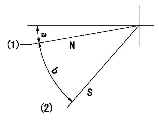
N:Pump normal
S:Stop the pump.
(1)Rack position = aa
(2)Rack position bb
----------
aa=20mm bb=1mm
----------
a=5deg+-5deg b=37deg+-5deg
----------
aa=20mm bb=1mm
----------
a=5deg+-5deg b=37deg+-5deg
0000000901

(1)Pump vertical direction
(2)Coupling's key groove position at No 1 cylinder's beginning of injection
(3)B.T.D.C.: aa
(4)-
----------
aa=8deg
----------
a=(4deg)
----------
aa=8deg
----------
a=(4deg)
Stop lever angle

(PWM) Pulse width modulation (%)
(R) Rack position (mm)
Rack sensor output characteristics
1. Rack limit adjustment
(1)Measure the rack position R2 for PWM a2%.
(2)Confirm that it is within the range R2 = 15+-1 mm.
(3)Measure the rack position R1 at PWM a %.
(4)Confirm that it is within the range R2 - R1 = 10+-0.1 mm.
2. Check the limp home operation.
(1)Move the switch box's limp home switch to the limp home side.
(2)Confirm rack position L1 (mm ) and L2 (mm) for PWM in the above table.
3. Check the pull down operation.
(1)Confirm that the rack position is 19 mm at PWM B%.
(2)In the conditions described in the above table, move the switch box's pull down switch to the pull down side and confirm that the rack position momentarily becomes 1 mm or less.
----------
a1=16.25% a2=72.5% L1=1--mm L2=19++mm A=5% B=95%
----------
----------
a1=16.25% a2=72.5% L1=1--mm L2=19++mm A=5% B=95%
----------
Information:
Removing delivery valve and spring(2) Inspection(a) Open the cock on the fuel filter. If the system has an electromagnetic pump, turn the key to the ON position. Fuel will flow out of the injection pipe. Make ready a container to catch it. If the system has an electromagnetic pump, caution is required since fuel will emerge with great force.(b) Slowly turn the crankshaft clockwise. The injection timing is reached when fuel stops flowing out. When fuel has stopped flowing out, turn the crankshaft slightly in the reverse direction such that fuel flows out. Then, slowly turn the crankshaft clockwise again to more accurately verify the point at which stops flowing out.
Fuel flow
End of fuel flow(c) If the IT mark on the crankshaft pulley and the mark on the gear case are aligned when fuel stops flowing out, the injection timing is normal.
Timing marks(3) Adjustment(a) If the injection timing is out of specification, make adjustments by increasing or decreasing the thickness of the injection pump's mounting shim. A change of 0.1 mm in the shim thickness yields a change of approximately 1° in the injection timing.(b) Increasing the shim thickness retards the injection timing, and decreasing the shim thickness advances it. Shims are available in thicknesses of 0.2 mm (0.008 in.), 0.3 mm (0.012 in.), 0.4 mm (0.016 in.), and 0.8 mm (0.031 in.). The thicknesses are not indicated on the shims, so any shim should be measured with a vernier caliper before being used.
Before using any shim, apply sealant to both sides to prevent oil leakage.
(c) After making adjustments, check that the injection timing is correct.(d) Close the cock on the fuel filter, then fit the delivery valve spring and injection pipe in their original positions.
Injection timing adjustment shim
Adjusting injection timing1.4 Adjusting Idle Speed(1) Preparation for Adjustment(a) Warm up the engine until the coolant reaches a temperature of 60°C (140°F) or higher.(b) Make sure the valve clearances, injection timing, and injectors are normal.(2) Adjusting Low-Idle SpeedLoosen the lock nut on the idling set bolt, turn the bolt to achieve the specified low-idle speed (1,000 25 min-1), then tighten the lock nut to hold the bolt in that position.(3) Adjusting No-Load Maximum SpeedLoosen the lock nut on the high-speed set bolt, turn the bolt to achieve the specified no-load maximum speed (2870+30-10 min-1), then tighten the lock nut to hold the bolt in that position.
Adjusting idle speed1.5 Adjusting Fan Belt Tension(1) Press the fan belt with the specified force mid-way between the alternator pulley and crankshaft pulley, and observe the extent of deflection. (2) If the extent of deflection is out of specification, loosen the adjusting bolt and adjust the fan belt tension by moving the alternator. Retighten the adjusting bolt securely.
Adjusting fan belt tension2. Running in the Engine
After an overhaul, the engine should be tested and inspected on a dynamometer. This operation serves to run in the engine's major moving parts.2.1 Starting the Engine(1) Before starting the engine, check the coolant, engine oil, and fuel levels and
Have questions with 101608-6432?
Group cross 101608-6432 ZEXEL
Mitsubishi
Mitsubishi
Mitsubishi
Mitsubishi
101608-6432
9 400 613 472
ME441260
INJECTION-PUMP ASSEMBLY
6D16TL
6D16TL
