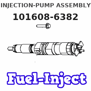
Information injection-pump assembly
BOSCH
F 019 Z20 022
f019z20022
ZEXEL
101608-6382
1016086382
MITSUBISHI
ME440900
me440900
Rating:
Service parts 101608-6382 INJECTION-PUMP ASSEMBLY:
1.
_

6.
COUPLING PLATE
7.
COUPLING PLATE
8.
_
9.
_

11.
Nozzle and Holder
12.
Open Pre:MPa(Kqf/cm2)
17.7(180)
15.
NOZZLE SET
Include in #1:
101608-6382
as INJECTION-PUMP ASSEMBLY
Include in #2:
104749-0695
as _
Cross reference number
BOSCH
F 019 Z20 022
f019z20022
ZEXEL
101608-6382
1016086382
MITSUBISHI
ME440900
me440900
Zexel num
Bosch num
Firm num
Name
101608-6382
F 019 Z20 022
ME440900 MITSUBISHI
INJECTION-PUMP ASSEMBLY
6D16TL K 14BN INJECTION PUMP ASSY PE
6D16TL K 14BN INJECTION PUMP ASSY PE
Calibration Data:
Adjustment conditions
Test oil
1404 Test oil ISO4113 or {SAEJ967d}
1404 Test oil ISO4113 or {SAEJ967d}
Test oil temperature
degC
40
40
45
Nozzle and nozzle holder
105780-8140
Bosch type code
EF8511/9A
Nozzle
105780-0000
Bosch type code
DN12SD12T
Nozzle holder
105780-2080
Bosch type code
EF8511/9
Opening pressure
MPa
17.2
Opening pressure
kgf/cm2
175
Injection pipe
Outer diameter - inner diameter - length (mm) mm 6-2-600
Outer diameter - inner diameter - length (mm) mm 6-2-600
Overflow valve
131424-5520
Overflow valve opening pressure
kPa
255
221
289
Overflow valve opening pressure
kgf/cm2
2.6
2.25
2.95
Tester oil delivery pressure
kPa
255
255
255
Tester oil delivery pressure
kgf/cm2
2.6
2.6
2.6
Direction of rotation (viewed from drive side)
Left L
Left L
Injection timing adjustment
Direction of rotation (viewed from drive side)
Left L
Left L
Injection order
1-5-3-6-
2-4
Pre-stroke
mm
4.5
4.45
4.55
Beginning of injection position
Governor side NO.1
Governor side NO.1
Difference between angles 1
Cal 1-5 deg. 60 59.5 60.5
Cal 1-5 deg. 60 59.5 60.5
Difference between angles 2
Cal 1-3 deg. 120 119.5 120.5
Cal 1-3 deg. 120 119.5 120.5
Difference between angles 3
Cal 1-6 deg. 180 179.5 180.5
Cal 1-6 deg. 180 179.5 180.5
Difference between angles 4
Cyl.1-2 deg. 240 239.5 240.5
Cyl.1-2 deg. 240 239.5 240.5
Difference between angles 5
Cal 1-4 deg. 300 299.5 300.5
Cal 1-4 deg. 300 299.5 300.5
Injection quantity adjustment
Adjusting point
A
Rack position
11.5
Pump speed
r/min
1075
1075
1075
Average injection quantity
mm3/st.
122.5
121.5
123.5
Max. variation between cylinders
%
0
-2.5
2.5
Basic
*
Fixing the lever
*
Boost pressure
kPa
65.3
65.3
Boost pressure
mmHg
490
490
Injection quantity adjustment_02
Adjusting point
-
Rack position
8.1+-0.5
Pump speed
r/min
430
430
430
Average injection quantity
mm3/st.
16.5
15
18
Max. variation between cylinders
%
0
-15
15
Fixing the rack
*
Boost pressure
kPa
0
0
0
Boost pressure
mmHg
0
0
0
Remarks
Adjust only variation between cylinders; adjust governor according to governor specifications.
Adjust only variation between cylinders; adjust governor according to governor specifications.
Injection quantity adjustment_03
Adjusting point
E
Rack position
11.7++
Pump speed
r/min
100
100
100
Average injection quantity
mm3/st.
105
105
115
Fixing the lever
*
Boost pressure
kPa
0
0
0
Boost pressure
mmHg
0
0
0
Rack limit
*
Boost compensator adjustment
Pump speed
r/min
450
450
450
Rack position
9.2
Boost pressure
kPa
12.7
6
19.4
Boost pressure
mmHg
95
45
145
Boost compensator adjustment_02
Pump speed
r/min
450
450
450
Rack position
10.5
Boost pressure
kPa
56
53.3
58.7
Boost pressure
mmHg
420
400
440
Timer adjustment
Pump speed
r/min
600
Advance angle
deg.
3
2.5
3.5
Load
0/4
Remarks
Start
Start
Timer adjustment_02
Pump speed
r/min
720
Advance angle
deg.
0.5
Load
0/4
Timer adjustment_03
Pump speed
r/min
(820)
Advance angle
deg.
0
0
0
Load
4/4
Timer adjustment_04
Pump speed
r/min
1000
Advance angle
deg.
1.5
1
2
Load
4/4
Remarks
Finish
Finish
Test data Ex:
Governor adjustment
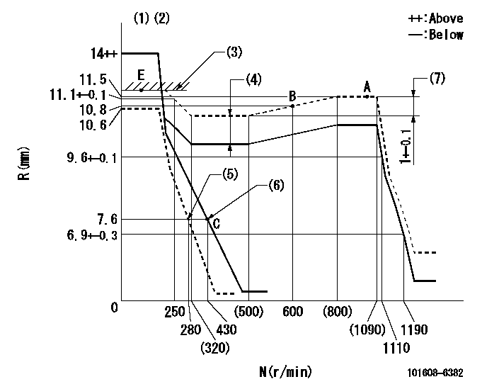
N:Pump speed
R:Rack position (mm)
(1)Target notch: K
(2)Tolerance for racks not indicated: +-0.05mm.
(3)RACK LIMIT
(4)Boost compensator stroke: BCL
(5)Set idle sub-spring
(6)Main spring setting
(7)Rack difference between N = N1 and N = N2
----------
K=11 BCL=1.3+-0.1mm N1=1075r/min N2=450r/min
----------
----------
K=11 BCL=1.3+-0.1mm N1=1075r/min N2=450r/min
----------
Speed control lever angle
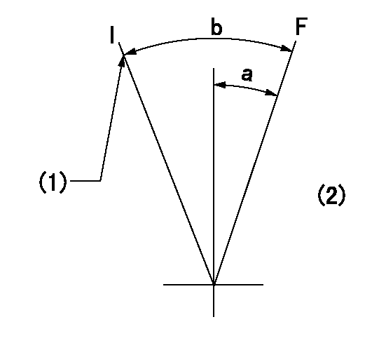
F:Full speed
I:Idle
(1)Stopper bolt setting
(2)Base lever only
----------
----------
a=5deg+-5deg b=21deg+-5deg
----------
----------
a=5deg+-5deg b=21deg+-5deg
Stop lever angle
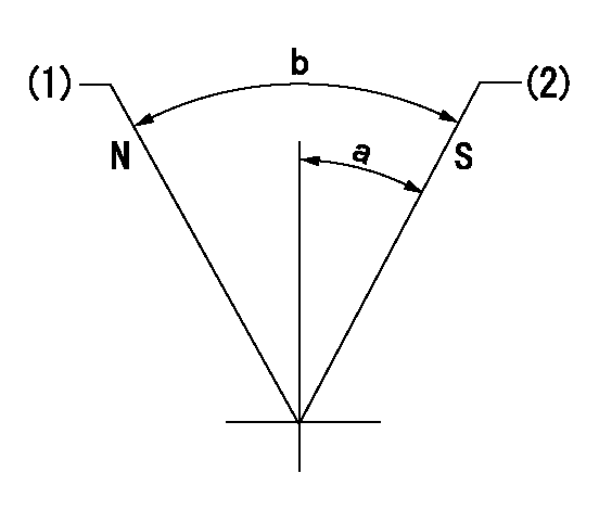
N:Pump normal
S:Stop the pump.
(1)Normal
(2)Pump speed aa and rack position bb (to be sealed at delivery)
----------
aa=0r/min bb=4-0.5mm
----------
a=28deg+-5deg b=(48deg)
----------
aa=0r/min bb=4-0.5mm
----------
a=28deg+-5deg b=(48deg)
Timing setting

(1)Pump vertical direction
(2)Coupling's key groove position at No 1 cylinder's beginning of injection
(3)B.T.D.C.: aa
(4)-
----------
aa=8deg
----------
a=(0deg)
----------
aa=8deg
----------
a=(0deg)
Information:
The serial number of any injector(s) replaced in a machine covered under this service letter must be documented in the claims story. Only injectors with serial numbers between 11577640-11676551 (see action required for explanation on how to decode injector serial number) will be allowed to be claimed under this service letter.
If there has been a previous repair, part age will apply. Retain a copy of the previous repair in the dealer's records for audit purposes, and specify repair date and machine hours in the "Additional Comments" section of the warranty claim.
Product smu/age whichever comes first Caterpillar Dealer Suggested Customer Suggested
Parts % Labor Hrs% Parts % Labor Hrs% Parts % Labor Hrs%
*******Group 3*******
0-1000 hrs,
0-24 mo 100.0% 100.0% 0.0% 0.0% 0.0% 0.0%
This is a 4.0-hour job for Group 3
The serial number of any injector(s) replaced in a machine covered under this service letter must be documented in the claims story. Only injectors with serial numbers between 11577640-11676551 (see action required for explanation on how to decode injector serial number) will be allowed to be claimed under this service letter.
If there has been a previous repair, part age will apply. Retain a copy of the previous repair in the dealer's records for audit purposes, and specify repair date and machine hours in the "Additional Comments" section of the warranty claim.
Product smu/age whichever comes first Caterpillar Dealer Suggested Customer Suggested
Parts % Labor Hrs% Parts % Labor Hrs% Parts % Labor Hrs%
*******Group 4*******
0-1000 hrs,
0-24 mo 100.0% 100.0% 0.0% 0.0% 0.0% 0.0%
This is a 4.0-hour job for Group 4
The serial number of any injector(s) replaced in a machine covered under this service letter must be documented in the claims story. Only injectors with serial numbers between 11577640-11676551 (see action required for explanation on how to decode injector serial number) will be allowed to be claimed under this service letter.
If there has been a previous repair, part age will apply. Retain a copy of the previous repair in the dealer's records for audit purposes, and specify repair date and machine hours in the "Additional Comments" section of the warranty claim.
PARTS DISPOSITION
Handle the parts in accordance with your Warranty Bulletin on warranty parts handling.
Have questions with 101608-6382?
Group cross 101608-6382 ZEXEL
Mitsubishi
Mitsubishi
Mitsubishi
Mitsubishi
Mitsubishi
Mitsubishi
Mitsubishi
Mitsubishi
101608-6382
F 019 Z20 022
ME440900
INJECTION-PUMP ASSEMBLY
6D16TL
6D16TL