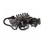
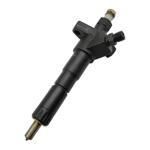
Information injection-pump assembly
BOSCH
9 400 613 377
9400613377
ZEXEL
101608-6352
1016086352
Rating:
Service parts 101608-6352 INJECTION-PUMP ASSEMBLY:
1.
_
7.
COUPLING PLATE
8.
_
9.
_
11.
Nozzle and Holder
12.
Open Pre:MPa(Kqf/cm2)
17.7{180}
15.
NOZZLE SET
Include in #1:
101608-6352
as INJECTION-PUMP ASSEMBLY
Include in #2:
104749-0444
as _
Cross reference number
BOSCH
9 400 613 377
9400613377
ZEXEL
101608-6352
1016086352
Zexel num
Bosch num
Firm num
Name
Calibration Data:
Adjustment conditions
Test oil
1404 Test oil ISO4113 or {SAEJ967d}
1404 Test oil ISO4113 or {SAEJ967d}
Test oil temperature
degC
40
40
45
Nozzle and nozzle holder
105780-8140
Bosch type code
EF8511/9A
Nozzle
105780-0000
Bosch type code
DN12SD12T
Nozzle holder
105780-2080
Bosch type code
EF8511/9
Opening pressure
MPa
17.2
Opening pressure
kgf/cm2
175
Injection pipe
Outer diameter - inner diameter - length (mm) mm 6-2-600
Outer diameter - inner diameter - length (mm) mm 6-2-600
Overflow valve
131424-5520
Overflow valve opening pressure
kPa
255
221
289
Overflow valve opening pressure
kgf/cm2
2.6
2.25
2.95
Tester oil delivery pressure
kPa
255
255
255
Tester oil delivery pressure
kgf/cm2
2.6
2.6
2.6
RED4 control unit part number
407915-0
590
RED4 rack sensor specifications
mm
19
Direction of rotation (viewed from drive side)
Left L
Left L
Injection timing adjustment
Direction of rotation (viewed from drive side)
Left L
Left L
Injection order
1-5-3-6-
2-4
Pre-stroke
mm
4.2
4.15
4.25
Beginning of injection position
Governor side NO.1
Governor side NO.1
Difference between angles 1
Cal 1-5 deg. 60 59.5 60.5
Cal 1-5 deg. 60 59.5 60.5
Difference between angles 2
Cal 1-3 deg. 120 119.5 120.5
Cal 1-3 deg. 120 119.5 120.5
Difference between angles 3
Cal 1-6 deg. 180 179.5 180.5
Cal 1-6 deg. 180 179.5 180.5
Difference between angles 4
Cyl.1-2 deg. 240 239.5 240.5
Cyl.1-2 deg. 240 239.5 240.5
Difference between angles 5
Cal 1-4 deg. 300 299.5 300.5
Cal 1-4 deg. 300 299.5 300.5
Injection quantity adjustment
Rack position
(11.1)
PWM
%
50.4
Pump speed
r/min
900
900
900
Average injection quantity
mm3/st.
124.5
123.5
125.5
Max. variation between cylinders
%
0
-2.5
2.5
Basic
*
Injection quantity adjustment_02
Rack position
(7.3)
PWM
%
29.4+-2.
8
Pump speed
r/min
425
425
425
Average injection quantity
mm3/st.
11
9.5
12.5
Max. variation between cylinders
%
0
-15
15
Governor adjustment
Pump speed
r/min
600
Advance angle
deg.
3
2.5
3.5
Load
0/4
Remarks
Start
Start
Governor adjustment_02
Pump speed
r/min
-
Advance angle
deg.
0
0
0
Load
0/4
Remarks
Measure the actual speed.
Measure the actual speed.
Governor adjustment_03
Pump speed
r/min
850
Advance angle
deg.
0.5
Load
4/4
Governor adjustment_04
Pump speed
r/min
1025
Advance angle
deg.
1.5
1
2
Load
4/4
Remarks
Finish
Finish
Test data Ex:
Speed control lever angle
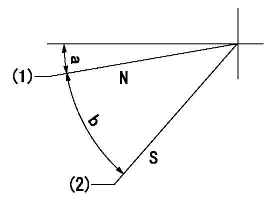
N:Pump normal
S:Stop the pump.
(1)Rack position = aa
(2)Rack position bb
----------
aa=20mm bb=1mm
----------
a=5deg+-5deg b=37deg+-5deg
----------
aa=20mm bb=1mm
----------
a=5deg+-5deg b=37deg+-5deg
0000000901

(1)Pump vertical direction
(2)Coupling's key groove position at No 1 cylinder's beginning of injection
(3)B.T.D.C.: aa
(4)-
----------
aa=8deg
----------
a=(0deg)
----------
aa=8deg
----------
a=(0deg)
Stop lever angle

(PWM) Pulse width modulation (%)
(R) Rack position (mm)
Rack sensor output characteristics
1. Rack limit adjustment
(1)Measure the rack position R2 for PWM a2%.
(2)Confirm that it is within the range R2 = 15+-1 mm.
(3)Measure the rack position R1 at PWM a %.
(4)Confirm that it is within the range R2 - R1 = 10+-0.1 mm.
2. Check the limp home operation.
(1)Move the switch box's limp home switch to the limp home side.
(2)Confirm rack position L1 (mm ) and L2 (mm) for PWM in the above table.
3. Check the pull down operation.
(1)Confirm that the rack position is 19 mm at PWM B%.
(2)In the conditions described in the above table, move the switch box's pull down switch to the pull down side and confirm that the rack position momentarily becomes 1 mm or less.
----------
a1=16.25% a2=72.5% L1=1--mm L2=19++mm A=5% B=95%
----------
----------
a1=16.25% a2=72.5% L1=1--mm L2=19++mm A=5% B=95%
----------
Information:
Vertical Tachometer Drive
Removal
Fig. 1-Vertical Tachometer DriveRemove cap (1, Fig. 1). Lift gasket (2) out of adapter (3).Turn adapter counterclockwise to remove it. Remove aluminum washer (4). Lift pinion (5) out of flywheel housing (6).Repair
Inspect parts for damage. Replace damaged parts.Installation
Coat pinion with engine oil. Put pinion in flywheel housing so that end of pinion rests on machined pad (7) in flywheel housing. Make sure gear teeth on pinion engage teeth on drive gear. IMPORTANT: Adapter can be installed easily only if gears are in mesh.Put aluminum washer over bottom of adapter. Install adapter in flywheel housing. Tighten adapter securely.Flywheel
Removal
If engine is equipped with a clutch, remove the clutch (Group 4052).
Fig. 2-Flywheel Cap ScrewRemove two cap screws (1, Fig. 2) that hold flywheel on crankshaft. Install two pilot studs through flywheel into crankshaft. Tighten pilot studs securely.
Flywheel weighs 50 to 85 lb. (23 to 39 kg). Plan proper handling procedures to avoid injury.
Remove remaining cap screws (2) that hold flywheel on crankshaft.Install two of the cap screws removed in threaded holes in flywheel. Tighten cap screws evenly to push flywheel off crankshaft.Repair
If engine is equipped with a clutch, inspect clutch contact face on flywheel for scoring, overheating, and cracking.
Fig. 3-Flywheel ThicknessClutch contact face can be resurfaced if there is heat checking. Minimum thickness of flywheel at clutch contact face is: IMPORTANT: If heat checks or cracks can be seen after resurfacing flywheel to minimum thickness, install a new flywheel.Inspect ring gear for worn or broken teeth. If damaged, install a new one (Group 0433).Installation
Install two guide studs in crankshaft rear flange. Tighten guide studs securely.
Flywheel weighs 50 to 85 lb. (23 to 39 kg). Plan proper handling procedure to avoid injury.
Move flywheel into position on guide studs. Push flywheel against crankshaft. IMPORTANT: Install new cap screws each time flywheel is removed.
Fig. 4-Flywheel Cap ScrewInstall cap screws and washers. Tighten cap screws evenly to secure flywheel to crankshaft.Remove guide studs from crankshaft. Install remaining cap screws. Tighten cap screws to 120 lb-ft (163 N m).Install clutch, if used (Group 4052).Flywheel Ring Gear
Removal
Remove flywheel (Group 0433).
Fig. 5-Remove Ring GearSelect a hardwood block (1, Fig. 5) that is slightly smaller than the inside diameter of the ring gear (2). Lay the flywheel, crankshaft side down, on the hardwood block.Using a drift and hammer (3), drive the ring gear off the flywheel. Move drift and hammer around ring gear often to prevent cocking the gear on the flywheel.Installation
Oil fumes or oil can ignite above 380°F (193°C). Use a thermometer and do not exceed 360°F (182°C). Do not allow a flame or heating element to be in direct contact with the oil. Heat the oil in a well-ventilated area. Plan a safe handling procedure to avoid burns.
Fig. 6-ChamferHeat new ring gear evenly in oil (to 360°F [182°C] maximum) or in oven (to 450°F [232°C] maximum) and install hot, with ring gear tooth chamfer (Fig. 6) toward engine side of flywheel. Drive ring gear onto flywheel evenly until it bottoms all the way around on
Removal
Fig. 1-Vertical Tachometer DriveRemove cap (1, Fig. 1). Lift gasket (2) out of adapter (3).Turn adapter counterclockwise to remove it. Remove aluminum washer (4). Lift pinion (5) out of flywheel housing (6).Repair
Inspect parts for damage. Replace damaged parts.Installation
Coat pinion with engine oil. Put pinion in flywheel housing so that end of pinion rests on machined pad (7) in flywheel housing. Make sure gear teeth on pinion engage teeth on drive gear. IMPORTANT: Adapter can be installed easily only if gears are in mesh.Put aluminum washer over bottom of adapter. Install adapter in flywheel housing. Tighten adapter securely.Flywheel
Removal
If engine is equipped with a clutch, remove the clutch (Group 4052).
Fig. 2-Flywheel Cap ScrewRemove two cap screws (1, Fig. 2) that hold flywheel on crankshaft. Install two pilot studs through flywheel into crankshaft. Tighten pilot studs securely.
Flywheel weighs 50 to 85 lb. (23 to 39 kg). Plan proper handling procedures to avoid injury.
Remove remaining cap screws (2) that hold flywheel on crankshaft.Install two of the cap screws removed in threaded holes in flywheel. Tighten cap screws evenly to push flywheel off crankshaft.Repair
If engine is equipped with a clutch, inspect clutch contact face on flywheel for scoring, overheating, and cracking.
Fig. 3-Flywheel ThicknessClutch contact face can be resurfaced if there is heat checking. Minimum thickness of flywheel at clutch contact face is: IMPORTANT: If heat checks or cracks can be seen after resurfacing flywheel to minimum thickness, install a new flywheel.Inspect ring gear for worn or broken teeth. If damaged, install a new one (Group 0433).Installation
Install two guide studs in crankshaft rear flange. Tighten guide studs securely.
Flywheel weighs 50 to 85 lb. (23 to 39 kg). Plan proper handling procedure to avoid injury.
Move flywheel into position on guide studs. Push flywheel against crankshaft. IMPORTANT: Install new cap screws each time flywheel is removed.
Fig. 4-Flywheel Cap ScrewInstall cap screws and washers. Tighten cap screws evenly to secure flywheel to crankshaft.Remove guide studs from crankshaft. Install remaining cap screws. Tighten cap screws to 120 lb-ft (163 N m).Install clutch, if used (Group 4052).Flywheel Ring Gear
Removal
Remove flywheel (Group 0433).
Fig. 5-Remove Ring GearSelect a hardwood block (1, Fig. 5) that is slightly smaller than the inside diameter of the ring gear (2). Lay the flywheel, crankshaft side down, on the hardwood block.Using a drift and hammer (3), drive the ring gear off the flywheel. Move drift and hammer around ring gear often to prevent cocking the gear on the flywheel.Installation
Oil fumes or oil can ignite above 380°F (193°C). Use a thermometer and do not exceed 360°F (182°C). Do not allow a flame or heating element to be in direct contact with the oil. Heat the oil in a well-ventilated area. Plan a safe handling procedure to avoid burns.
Fig. 6-ChamferHeat new ring gear evenly in oil (to 360°F [182°C] maximum) or in oven (to 450°F [232°C] maximum) and install hot, with ring gear tooth chamfer (Fig. 6) toward engine side of flywheel. Drive ring gear onto flywheel evenly until it bottoms all the way around on
