Information injection-pump assembly
BOSCH
F 019 Z20 020
f019z20020
ZEXEL
101608-6333
1016086333
MITSUBISHI
ME442644
me442644
Rating:
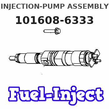
Service parts 101608-6333 INJECTION-PUMP ASSEMBLY:
1.
_
7.
COUPLING PLATE
8.
_
9.
_
11.
Nozzle and Holder
12.
Open Pre:MPa(Kqf/cm2)
17.7{180}
15.
NOZZLE SET
Include in #1:
101608-6333
as INJECTION-PUMP ASSEMBLY
Include in #2:
104749-0425
as _
Cross reference number
BOSCH
F 019 Z20 020
f019z20020
ZEXEL
101608-6333
1016086333
MITSUBISHI
ME442644
me442644
Zexel num
Bosch num
Firm num
Name
F 019 Z20 020
ME442644 MITSUBISHI
INJECTION-PUMP ASSEMBLY
6D16TL * K 14BN INJECTION PUMP ASSY PE
6D16TL * K 14BN INJECTION PUMP ASSY PE
Calibration Data:
Adjustment conditions
Test oil
1404 Test oil ISO4113 or {SAEJ967d}
1404 Test oil ISO4113 or {SAEJ967d}
Test oil temperature
degC
40
40
45
Nozzle and nozzle holder
105780-8140
Bosch type code
EF8511/9A
Nozzle
105780-0000
Bosch type code
DN12SD12T
Nozzle holder
105780-2080
Bosch type code
EF8511/9
Opening pressure
MPa
17.2
Opening pressure
kgf/cm2
175
Injection pipe
Outer diameter - inner diameter - length (mm) mm 6-2-600
Outer diameter - inner diameter - length (mm) mm 6-2-600
Overflow valve
131424-5520
Overflow valve opening pressure
kPa
255
221
289
Overflow valve opening pressure
kgf/cm2
2.6
2.25
2.95
Tester oil delivery pressure
kPa
255
255
255
Tester oil delivery pressure
kgf/cm2
2.6
2.6
2.6
Direction of rotation (viewed from drive side)
Left L
Left L
Injection timing adjustment
Direction of rotation (viewed from drive side)
Left L
Left L
Injection order
1-5-3-6-
2-4
Pre-stroke
mm
4.5
4.45
4.55
Beginning of injection position
Governor side NO.1
Governor side NO.1
Difference between angles 1
Cal 1-5 deg. 60 59.5 60.5
Cal 1-5 deg. 60 59.5 60.5
Difference between angles 2
Cal 1-3 deg. 120 119.5 120.5
Cal 1-3 deg. 120 119.5 120.5
Difference between angles 3
Cal 1-6 deg. 180 179.5 180.5
Cal 1-6 deg. 180 179.5 180.5
Difference between angles 4
Cyl.1-2 deg. 240 239.5 240.5
Cyl.1-2 deg. 240 239.5 240.5
Difference between angles 5
Cal 1-4 deg. 300 299.5 300.5
Cal 1-4 deg. 300 299.5 300.5
Injection quantity adjustment
Adjusting point
A
Rack position
11.5
Pump speed
r/min
1400
1400
1400
Average injection quantity
mm3/st.
116
115
117
Max. variation between cylinders
%
0
-2.5
2.5
Basic
*
Fixing the lever
*
Boost pressure
kPa
54.7
54.7
Boost pressure
mmHg
410
410
Injection quantity adjustment_02
Adjusting point
C
Rack position
8.1+-0.5
Pump speed
r/min
325
325
325
Average injection quantity
mm3/st.
8.5
7
10
Max. variation between cylinders
%
0
-15
15
Fixing the rack
*
Boost pressure
kPa
0
0
0
Boost pressure
mmHg
0
0
0
Injection quantity adjustment_03
Adjusting point
E
Rack position
11.7++
Pump speed
r/min
100
100
100
Average injection quantity
mm3/st.
95
95
105
Fixing the lever
*
Boost pressure
kPa
0
0
0
Boost pressure
mmHg
0
0
0
Rack limit
*
Boost compensator adjustment
Pump speed
r/min
650
650
650
Rack position
9.5
Boost pressure
kPa
15.3
8.6
22
Boost pressure
mmHg
115
65
165
Boost compensator adjustment_02
Pump speed
r/min
650
650
650
Rack position
10.7
Boost pressure
kPa
45.3
42.6
48
Boost pressure
mmHg
340
320
360
Timer adjustment
Pump speed
r/min
1070--
Advance angle
deg.
0
0
0
Load
4/4
Remarks
Beginning of advance.
Beginning of advance.
Timer adjustment_02
Pump speed
r/min
440
Advance angle
deg.
3
2.5
3.5
Load
0/4
Remarks
Start
Start
Timer adjustment_03
Pump speed
r/min
-
Advance angle
deg.
0
0
0
Load
0/4
Remarks
Measure the actual speed.
Measure the actual speed.
Timer adjustment_04
Pump speed
r/min
1020
Advance angle
deg.
0.5
Load
4/4
Timer adjustment_05
Pump speed
r/min
1330
Advance angle
deg.
3
2.5
3.5
Load
4/4
Remarks
Finish
Finish
Test data Ex:
Governor adjustment
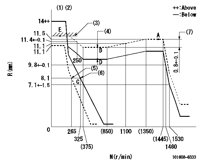
N:Pump speed
R:Rack position (mm)
(1)Notch fixed: K
(2)Tolerance for racks not indicated: +-0.05mm.
(3)RACK LIMIT
(4)Boost compensator stroke: BCL
(5)Set idle sub-spring
(6)Main spring setting
(7)Rack difference between N = N1 and N = N2
----------
K=11 BCL=1.2+-0.1mm N1=1400r/min N2=650r/min
----------
----------
K=11 BCL=1.2+-0.1mm N1=1400r/min N2=650r/min
----------
Speed control lever angle
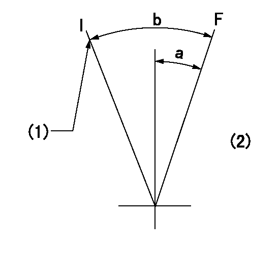
F:Full speed
I:Idle
(1)Stopper bolt setting
(2)Base lever only
----------
----------
a=(17deg)+-5deg b=(34deg)+-5deg
----------
----------
a=(17deg)+-5deg b=(34deg)+-5deg
Stop lever angle
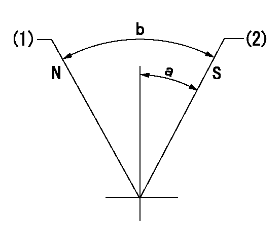
N:Pump normal
S:Stop the pump.
(1)Normal
(2)Pump speed aa and rack position bb (to be sealed at delivery)
----------
aa=0r/min bb=4-0.5mm
----------
a=28deg+-5deg b=(48deg)
----------
aa=0r/min bb=4-0.5mm
----------
a=28deg+-5deg b=(48deg)
Timing setting

(1)Pump vertical direction
(2)Coupling's key groove position at No 1 cylinder's beginning of injection
(3)B.T.D.C.: aa
(4)-
----------
aa=6.5deg
----------
a=(3deg)
----------
aa=6.5deg
----------
a=(3deg)
Information:
Removal
Disconnect battery negative (-) cable at the battery terminal.Allow engine to cool.Drain cooling system.Remove alternator, fan belts, fan and sheet metal fan pulley.
Fig. 1-Bypass HoseDisconnect cooling system bypass hose (Fig. 1) at top of water pump.Disconnect lower radiator hose at water pump and engine oil cooler hose at lower rear of water pump (1, Fig. 2).
Fig. 2-Water Pump RemovalRemove water pump attaching hardware (2, Fig. 2) and remove water pump from engine.Disassembly
Fig. 3-Cover Plate RemovalRemove cover plate cap screws (1, Fig. 3). Lift cover plate (2) and gasket (3) off water pump.3-164D, 3-179D, 4-219D, 4-239D, 4-276D, or 6-329D Engine
Fig. 4-D01200AA PullerUsing D01200AA Puller (Fig. 4), remove pulley or pulley hub.
Fig. 5-JD262A Bearing DriverSupport housing from impeller end. Using JD262A Bearing Driver (Fig. 5), push bearing and impeller out of housing from pulley end.
Fig. 6-0.5 in. (13 mm) DriftSupport impeller from bearing side. Using a 0.5 in. (13 mm) drift (Fig. 6), push bearing shaft out of impeller.Lift seal off bearing shaft.4-239T, 4-276T, 6-359D, 6-359T, 6-414D, or 6-414T Engine
Fig. 7-D01200AA PullerUsing D01200AA Puller, remove pulley. IMPORTANT: Do not attempt to push shaft from pulley end. A flange in the bearing bore prevents bearing passage through housing.
Fig. 8-D01200AA PullerUsing D01200AA Puller, remove impeller.
Fig. 9-Bearing ShaftSupport pulley end of housing. Select a 0.5 in. (13 mm) diameter by 3.0 in. (76 mm) drift. Push against impeller end of bearing shaft (Fig. 9) to push bearing out of housing. IMPORTANT: Always replace a bearing that has been removed from pump.Repair
Fig. 10-Seal and InsertsInspect seal (2, Fig. 10) and ceramic insert (1) for damage. The lapped surfaces can not be grooved, chipped, cracked, or scratched.If there are traces of coolant on bearing or if there was leakage from drain hole in bottom of housing, the seal is leaking.To remove metal type seal, use a punch to drive it out of the housing from the bearing side.To remove rubber type seal, peel it out of the housing from the impeller side.If seal is replaced, also remove ceramic insert and cupped rubber insert from counterbore in impeller.Inspect housing for damage behind impeller. Replace housing and impeller if metal has been scrapped away. IMPORTANT: Always replace bearing that has been removed from pump.Assembly
IMPORTANT: Do not push against end of bearing shaft. Push against outer race only.
Fig. 11-JD262A or JDE74 Bearing DriverFor water pumps on engines 3-164D, 3-179D, 4-219D, 4-239D, 4-276D and 6-329D, use JD262A Bearing Driver (Fig. 11).For water pumps on engines 4-239T, 4-276T, 6-359D, 6-359T, 6-414D and 6-414T, use JDE74 Bearing Driver (Fig. 11).Push bearing into housing until outer end of bearing is flush with the housing. IMPORTANT: Do not touch lapped surface of seal.
Fig. 12-SealSparingly coat the flange portion of the seal with joint sealing compound. Press seal into housing by hand until flange bottoms on housing (Fig. 12). Wipe away any excess joint sealing compound.
Fig. 13-InsertsPlace ceramic insert in cupped rubber insert with "V" groove on ceramic insert toward cupped rubber insert. Be sure parts are dry and clean.Dip inserts in light oil
