Information injection-pump assembly
BOSCH
9 400 612 986
9400612986
ZEXEL
101608-6321
1016086321
Rating:
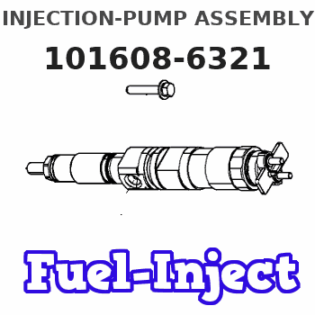
Service parts 101608-6321 INJECTION-PUMP ASSEMBLY:
1.
_
7.
COUPLING PLATE
8.
_
9.
_
11.
Nozzle and Holder
ME440071
12.
Open Pre:MPa(Kqf/cm2)
17.7{180}
15.
NOZZLE SET
Include in #1:
101608-6321
as INJECTION-PUMP ASSEMBLY
Include in #2:
104748-0550
as _
Cross reference number
BOSCH
9 400 612 986
9400612986
ZEXEL
101608-6321
1016086321
Zexel num
Bosch num
Firm num
Name
Calibration Data:
Adjustment conditions
Test oil
1404 Test oil ISO4113 or {SAEJ967d}
1404 Test oil ISO4113 or {SAEJ967d}
Test oil temperature
degC
40
40
45
Nozzle and nozzle holder
105780-8140
Bosch type code
EF8511/9A
Nozzle
105780-0000
Bosch type code
DN12SD12T
Nozzle holder
105780-2080
Bosch type code
EF8511/9
Opening pressure
MPa
17.2
Opening pressure
kgf/cm2
175
Injection pipe
Outer diameter - inner diameter - length (mm) mm 6-2-600
Outer diameter - inner diameter - length (mm) mm 6-2-600
Overflow valve
131424-5520
Overflow valve opening pressure
kPa
255
221
289
Overflow valve opening pressure
kgf/cm2
2.6
2.25
2.95
Tester oil delivery pressure
kPa
255
255
255
Tester oil delivery pressure
kgf/cm2
2.6
2.6
2.6
Direction of rotation (viewed from drive side)
Left L
Left L
Injection timing adjustment
Direction of rotation (viewed from drive side)
Left L
Left L
Injection order
1-5-3-6-
2-4
Pre-stroke
mm
4.5
4.45
4.55
Beginning of injection position
Governor side NO.1
Governor side NO.1
Difference between angles 1
Cal 1-5 deg. 60 59.5 60.5
Cal 1-5 deg. 60 59.5 60.5
Difference between angles 2
Cal 1-3 deg. 120 119.5 120.5
Cal 1-3 deg. 120 119.5 120.5
Difference between angles 3
Cal 1-6 deg. 180 179.5 180.5
Cal 1-6 deg. 180 179.5 180.5
Difference between angles 4
Cyl.1-2 deg. 240 239.5 240.5
Cyl.1-2 deg. 240 239.5 240.5
Difference between angles 5
Cal 1-4 deg. 300 299.5 300.5
Cal 1-4 deg. 300 299.5 300.5
Injection quantity adjustment
Adjusting point
A
Rack position
11.1
Pump speed
r/min
1050
1050
1050
Average injection quantity
mm3/st.
107.5
106.5
108.5
Max. variation between cylinders
%
0
-2.5
2.5
Basic
*
Fixing the lever
*
Boost pressure
kPa
65.3
65.3
Boost pressure
mmHg
490
490
Injection quantity adjustment_02
Adjusting point
-
Rack position
8+-0.5
Pump speed
r/min
495
495
495
Average injection quantity
mm3/st.
16.5
15
18
Max. variation between cylinders
%
0
-15
15
Fixing the rack
*
Boost pressure
kPa
0
0
0
Boost pressure
mmHg
0
0
0
Remarks
Adjust only variation between cylinders; adjust governor according to governor specifications.
Adjust only variation between cylinders; adjust governor according to governor specifications.
Injection quantity adjustment_03
Adjusting point
E
Rack position
11.3++
Pump speed
r/min
100
100
100
Average injection quantity
mm3/st.
105
105
115
Fixing the lever
*
Boost pressure
kPa
0
0
0
Boost pressure
mmHg
0
0
0
Rack limit
*
Boost compensator adjustment
Pump speed
r/min
375
375
375
Rack position
9.35
Boost pressure
kPa
24
17.3
30.7
Boost pressure
mmHg
180
130
230
Boost compensator adjustment_02
Pump speed
r/min
375
375
375
Rack position
10.4
Boost pressure
kPa
56
53.3
58.7
Boost pressure
mmHg
420
400
440
Timer adjustment
Pump speed
r/min
600
Advance angle
deg.
3
2.5
3.5
Load
0/4
Remarks
Start
Start
Timer adjustment_02
Pump speed
r/min
720
Advance angle
deg.
0.5
Load
0/4
Timer adjustment_03
Pump speed
r/min
(820)
Advance angle
deg.
0
0
0
Load
4/4
Timer adjustment_04
Pump speed
r/min
1000
Advance angle
deg.
1.5
1
2
Load
4/4
Remarks
Finish
Finish
Test data Ex:
Governor adjustment
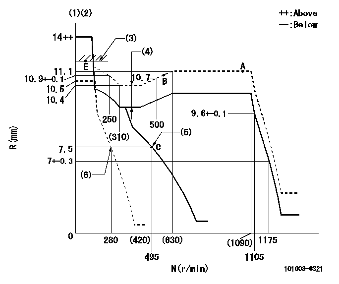
N:Pump speed
R:Rack position (mm)
(1)Target notch: K
(2)Tolerance for racks not indicated: +-0.05mm.
(3)RACK LIMIT
(4)Boost compensator stroke: BCL
(5)Main spring setting
(6)Set idle sub-spring
----------
K=10 BCL=1.05+-0.1mm
----------
----------
K=10 BCL=1.05+-0.1mm
----------
Speed control lever angle

F:Full speed
I:Idle
(1)Stopper bolt setting
----------
----------
a=18deg+-5deg b=3deg+-5deg
----------
----------
a=18deg+-5deg b=3deg+-5deg
Stop lever angle
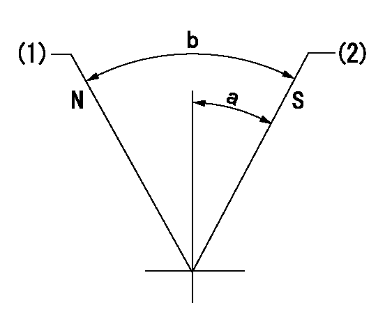
N:Pump normal
S:Stop the pump.
(1)Normal
(2)Pump speed aa and rack position bb (to be sealed at delivery)
----------
aa=0r/min bb=1-0.5mm
----------
a=35deg+-5deg b=(55deg)
----------
aa=0r/min bb=1-0.5mm
----------
a=35deg+-5deg b=(55deg)
0000001501 TAMPER PROOF

Tamperproofing-equipped boost compensator cover installation procedure
(A) After adjusting the boost compensator, tighten the bolts to remove the heads.
(1)Before adjusting the governor and the boost compensator, tighten the screw to the specified torque.
(Tightening torque T = T1 maximum)
(2)After adjusting the governor and the boost compensator, tighten to the specified torque to break off the bolt heads.
(Tightening torque T = T2 maximum)
----------
T1=2.5N-m(0.25kgf-m) T2=2.9~4.4N-m(0.3~0.45kgf-m)
----------
----------
T1=2.5N-m(0.25kgf-m) T2=2.9~4.4N-m(0.3~0.45kgf-m)
----------
Timing setting

(1)Pump vertical direction
(2)Coupling's key groove position at No 1 cylinder's beginning of injection
(3)B.T.D.C.: aa
(4)-
----------
aa=8deg
----------
a=(0deg)
----------
aa=8deg
----------
a=(0deg)
Information:
Repair
Pistons
See Group 0404 for piston-to-cylinder liner measurements.Remove piston rings. IMPORTANT: Do not soak pistons more than 60 minutes.
Avoid contact of solution with skin or eyes.
Soak pistons in 50 percent solution of "Mr. Clean" (or equivalent) and water for 30 to 60 minutes. IMPORTANT: Never clean pistons with wire brush or abrasives.Scrub piston with stiff bristle brush.Rinse pistons in clean water and dry with clean towels. Two different types of pistons marked "B" and "H" on their top face can be selectively installed on 3179D, 4239 D & T, and 6359 D & T engines for a better dead space control inside the cylinder. The difference between the two pistons is 0.006 inch (0.15 mm) on the distance between the piston pin center and the piston top.When replacing pistons, install pistons of the same type as the original.When replacing cylinder block or when mark on piston is no longer visible, determine piston type as follows using gauge KCD-10003.Install cylinder liners and crankshaft with bearings in cylinder block.Secure cylinder liners, using cap screws and washers.Install a "B" type piston with its connecting rod and secure with cap.
Fig. 3A-Determining Type of Piston Using Gauge KCD-10003Place gauge KCD-10003 on liner flange and press downward (3A).Turn crankshaft until piston is in "TDC" position.When piston lightly touches gauge then use "B" type pistons.When pisotn does not contact gauge, then use "H" type pistons.If no gauge is available, proceed as follows:Install a "B" type piston with its connecting rod and secure with cap.Using a dial indicator measure protrusion of each piston (at TDC) above face of cylinder block. Measure at cylinder block centerlineInstall a "B" type piston if protrusion is above or equal to 0.004 in. (0.1 mm) and an "H" type piston if protrusion is below 0.004 in. (0.1 mm). IMPORTANT: Maximum allowable piston standout is 0.012 in. (0.30 mm).Piston Rings and Ring Grooves
Do not re-use piston rings.
Fig. 4-JDE-62 Ring Groove Wear GaugeUsing JDE-62 Ring Groove Wear Gauge (Fig. 4), measure top ring groove. If gauge shoulders contact the ring land, groove is excessively worn.Measure rectangular ring grooves with proper new ring and a feeler gauge.
Fig. 5-Measure Ring GroovesRing groove clearance (maximum) (Fig. 5) ... 0.008 inch(0.20 mm)Piston Pin Bore
Fig. 6-Piston Pin AssemblyPiston pins must fit piston pin bore with a thumb press fit (Fig. 6).Replace piston if piston pin bore is worn.Piston Pin Bushing
Fig. 7-Piston PinMeasure piston pin bushing inside diameter (Fig. 8) with bushing in connecting rod.Piston pin bushing size; If piston pin size is not within specifications, install a new one.Piston Pin Bushing
Fig. 8-Piston Pin BushingMeasure piston pin bushing inside diameter (Fig. 8) with bushing in connecting rod.Piston pin bushing size; Check piston pin size (Group 0403, above).Find the difference, piston pin/bushing clearance, between the piston pin size and the bushing size. The clearance (Fig. 9) must be 0.0008 to 0.0022 in. (0.02 to 0.06 mm).
Fig. 9-Piston Pin/Bushing ClearanceIf bushing size is not within specifications, install a new one.
Fig. 10-Bushing Remover and InstallerUsing the bushing remover and installer listed below,
